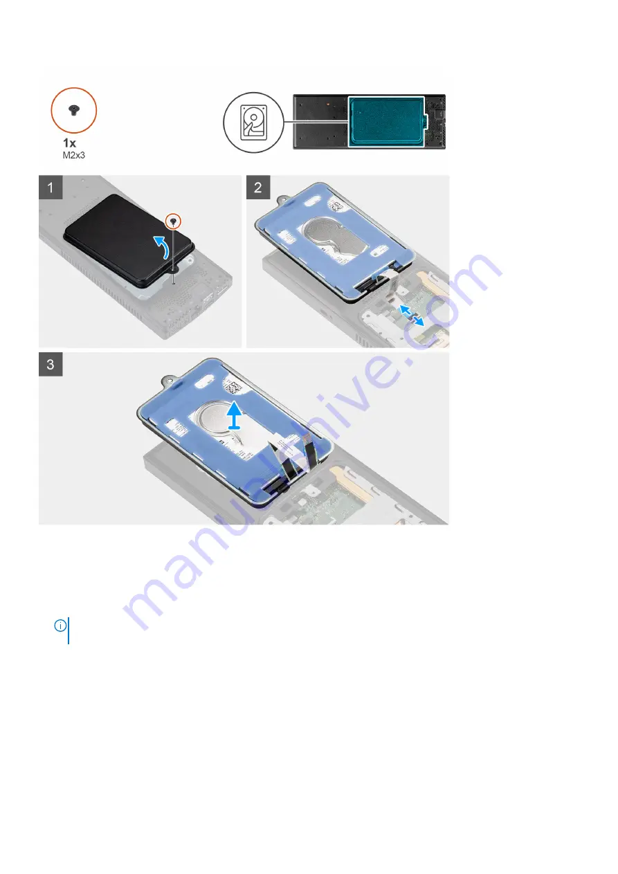
Steps
1. Remove the (M2x3) screw that secures the hard-drive assembly to the chassis.
2. Turn the hard-drive assembly to access the hard-drive cable.
3. Open the latch and disconnect the hard-drive cable from the connector on the system board.
4. Carefully unroute the hard-drive cable from the routing guide on the chassis.
NOTE:
Observe the routing of the hard-drive cable inside the chassis as you remove them. Route the cable properly
when you replace the component to prevent the cable from being pinched or crimped.
5. Remove the hard-drive assembly.
Installing the hard-drive assembly
Prerequisites
If you are replacing a component, remove the existing component before performing the installation procedure.
92
Removing and installing components
Summary of Contents for OptiPlex 3090 Ultra
Page 16: ...17 Lock the device and the stand cover 16 Stands ...
Page 17: ...18 Press the power button to turn on the device Stands 17 ...
Page 27: ...12 Slide the back cover along with the device into the stand until you hear a click Stands 27 ...
Page 28: ...13 Lock the device and the stand cover 28 Stands ...
Page 29: ...14 Press the power button to turn on the device Stands 29 ...
Page 39: ...Stands 39 ...
Page 40: ...40 Stands ...
Page 45: ...Stands 45 ...
Page 47: ...Stands 47 ...
Page 49: ...9 Slide and release the inner bar on the lower edge of the stand cover Stands 49 ...
Page 54: ...Large Height Adjustable Stand 54 Stands ...
Page 56: ...15 Lock the device and the stand cover 56 Stands ...
Page 57: ...16 Press the power button to turn on the device Stands 57 ...
Page 59: ...4 Disconnect the keyboard mouse network power and display cable from the device Stands 59 ...
Page 63: ...For 30 inch to 32 inch monitor Large height adjustable stand Stands 63 ...
Page 64: ...For monitors 32 inch Large height adjustable stand 64 Stands ...
Page 72: ...k Close the stand cover 72 Stands ...
Page 73: ...l Lock the device and the stand cover Stands 73 ...
Page 79: ...h Press the power button to turn on the device Stands 79 ...
Page 81: ...b Open the wall mount cover Stands 81 ...
Page 82: ...c Disconnect the keyboard mouse network power and display cable from the device 82 Stands ...
Page 83: ...d Snap open the wall mount bracket module from the slots on the wall mount Stands 83 ...
Page 90: ...Major components of your system 1 Cover 90 Removing and installing components ...


