background image

Follow the instructions on the screen.

Updating BIOS on systems with BitLocker enabled

CAUTION:

 If BitLocker is not suspended before updating the BIOS, the next time you reboot the system it will not

recognize the BitLocker key. You will then be prompted to enter the recovery key to progress and the system will ask for
this on each reboot. If the recovery key is not known, this can result in data loss or an unnecessary operating system
reinstall. For more information about this subject, see Knowledge Article: 

Updating the BIOS on Dell Systems With

BitLocker Enabled

Updating your system BIOS using a USB flash drive

If the system cannot load into Windows, but there is still a need to update the BIOS, download the BIOS file using another system and
save it to a bootable USB Flash Drive.

NOTE:

 You will need to use a bootable USB flash drive. Please refer to the following article for further details 

How to

Create a Bootable USB Flash Drive using Dell Diagnostic Deployment Package (DDDP)

1. Download the BIOS update .EXE file to another system.
2. Copy the file e.g. O9010A12.EXE onto the bootable USB flash drive.
3. Insert the USB flash drive into the system that requires the BIOS update.
4. Restart the system and press F12 when the Dell splash logo appears to display the One Time Boot Menu.
5. Using arrow keys, select 

USB Storage Device

 and click 

Enter

.

6. The system will boot to a Diag C:\> prompt.
7. Run the file by typing the full filename, for example, O9010A12.exe and press 

Enter

.

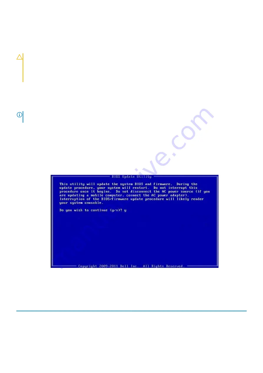
8. The BIOS Update Utility will load. Follow the instructions on screen.

Figure 1. DOS BIOS Update Screen

System and setup password

Table 37. System and setup password

Password type

Description

System password

Password that you must enter to log on to your system.

Setup password

Password that you must enter to access and make changes to the
BIOS settings of your computer.

36

System setup

Summary of Contents for Latitude 9410

Page 1: ...Dell Latitude 9410 Setup and specifications guide Regulatory Model P110G Regulatory Type P110G001 ...

Page 2: ...al damage to hardware or loss of data and tells you how to avoid the problem WARNING A WARNING indicates a potential for property damage personal injury or death 2020 Dell Inc or its subsidiaries All rights reserved Dell EMC and other trademarks are trademarks of Dell Inc or its subsidiaries Other trademarks may be trademarks of their respective owners Rev A00 ...

Page 3: ...t 14 Processors 14 Chipset 14 Operating system 15 Memory 15 Ports and connectors 15 Communications 16 Audio 17 Storage 17 Media card reader 18 Keyboard 18 Camera 18 Touchpad 19 Touchpad gestures 19 Power adapter 19 Battery 20 Display 20 Fingerprint reader 21 Video 22 Security 22 Security Software 22 Computer environment 22 6 System setup 24 Boot menu 24 Navigation keys 24 Boot Sequence 25 System s...

Page 4: ...eless options 34 Maintenance 34 System logs 35 Updating the BIOS in Windows 35 Updating BIOS on systems with BitLocker enabled 36 Updating your system BIOS using a USB flash drive 36 System and setup password 36 Assigning a system setup password 37 Deleting or changing an existing system setup password 37 ExpressSign in 37 7 Software 41 Downloading Windows drivers 41 8 Getting help 42 Contacting D...

Page 5: ...rompted If connected to the internet sign in with or create a Microsoft account If not connected to the internet create an offline account On the Support and Protection screen enter your contact details 4 Locate and use Dell apps from the Windows Start menu Recommended Table 1 Locate Dell apps Dell apps Details Dell Product Registration Register your computer with Dell Dell Help Support Access hel...

Page 6: ...ry Download software applications including software that is purchased but not pre installed on your computer 5 Create recovery drive for Windows NOTE It is recommended to create a recovery drive to troubleshoot and fix problems that may occur with Windows 6 For more information see Create a USB recovery drive for Windows 6 Set up your computer ...

Page 7: ... your computer 2 In Windows search type Recovery 3 In the search results click Create a recovery drive The User Account Control window is displayed 4 Click Yes to continue The Recovery Drive window is displayed 5 Select Back up system files to the recovery drive and click Next 6 Select the USB flash drive and click Next A message appears indicating that all data in the USB flash drive will be dele...

Page 8: ... 2 Gen 2 Type C port with Thunderbolt 3 3 HDMI 2 0 Port 4 USB 3 2 Gen 1 Type A port with PowerShare 5 Smart card reader optional Right view 1 Universal audio port 2 uSIM card slot WWAN only 3 uSD 4 0 card reader 4 USB 3 2 Gen 1 Type A port with PowerShare 5 Wedge shaped lock slot 3 8 Chassis overview ...

Page 9: ...Top view 1 Power button with fingerprint reader optional 2 Keyboard 3 Touchpad with NFC optional Chassis overview 9 ...

Page 10: ... Proximity sensor receiver 2 Proximity sensor emitter 3 IR emitter 4 Infrared camera 5 Camera status LED 6 IR emitter 7 Ambient Light Sensor ALS 8 Display panel 9 Battery Diagnostics status LED 10 Chassis overview ...

Page 11: ...Bottom view 1 Thermal vent 2 Service Tag label 3 Speakers Chassis overview 11 ...

Page 12: ...Chassis modes This section illustrates various supported modes for Latitude 7400 2 in 1 Stand Notebook Tablet and Tent 12 Chassis overview ...

Page 13: ...e Fn key lock Fn F1 Mute audio F1 behavior Fn F2 Decrease volume F2 behavior Fn F3 Increase volume F3 behavior Fn F4 Mic Mute F4 behavior Fn F5 Keyboard backlight NOTE Not applicable for non backlight keyboard F5 behavior Fn F6 Decrease screen brightness F6 behavior Fn F7 Increase screen brightness F7 behavior Fn F8 Display Toggle Win P F8 behavior Fn F10 Print Screen F10 behavior Fn F11 Home F11 ...

Page 14: ...re i5 10210U 10th Generation Intel Core i5 10310U 10th Generation Intel Core i7 10610U 10th Generation Intel Core i7 10810U Wattage 15 W 15 W 15 W 15 W Core count 4 4 4 6 Thread count 8 8 8 12 Speed 1 6 GHz to 4 2 GHz 1 6 GHz to 4 4 GHz 1 8 GHz to 4 9 GHz 1 1 GHz to 4 9 GHz Cache 6 MB 6 MB 8 MB 12 MB Integrated graphics Intel UHD Graphics Intel UHD Graphics Intel UHD Graphics Intel UHD Graphics Ch...

Page 15: ...PDDR3 SDRAM 2133 MHz on board Ports and connectors Table 7 External ports and connectors Description Values External USB 2 USB 3 2 Gen 1 Type A ports with Power Share 1 USB 3 2 Gen 2 Type C port with Power Delivery Thunderbolt 3 1 USB 3 2 Gen 2 Type C port with Thunderbolt 3 Audio 1 Universal Audio Jack Video 1 HDMI 2 0 Media card reader uSD 4 0 Docking port Thunderbolt Power adapter port 4 50 mm ...

Page 16: ... bit 128 bit WEP AES CCMP TKIP Bluetooth Bluetooth 5 0 Bluetooth 5 1 Wireless wide area network module Table 10 WWAN module specifications Description Values Model number Qualcomm Snapdragon X20 Global Gigabit LTE A Form factor M 2 3042 Key B single side Transfer rate Up to 1 Gbps DL 150 Mbps UL Cat 16 Operating Frequency bands supported 1 2 3 4 5 7 8 12 13 14 17 18 19 20 25 26 28 29 30 32 38 39 4...

Page 17: ...M 2 2230 512 GB Gen 3 PCIe x4 NVMe Class 35 SSD M 2 2230 512 GB Gen 3 PCIe x4 NVMe Class 35 SSD M 2 2230 1 TB Gen 3 PCIe x4 NVMe Class 35 SSD M 2 2230 256 GB Gen 3 PCIe x4 NVMe Class 35 Self Encrypting SSD M 2 2280 256 GB Gen 3 PCIe x4 NVMe Class 40 SSD M 2 2280 512 GB Gen 3 PCIe x4 NVMe Class 40 SSD M 2 2280 1 TB Gen 3 PCIe x4 NVMe Class 40 SSD M 2 2280 2 TB Gen 3 PCIe x4 NVMe Class 40 SSD M 2 22...

Page 18: ...on them These keys can be used to type alternate characters or to perform secondary functions To type the alternate character press Shift and the desired key To perform secondary functions press Fn and the desired key NOTE You can define the primary behavior of the function keys F1 F12 changing Function Key Behavior in BIOS setup program Keyboard shortcuts Camera Table 15 Camera specifications Des...

Page 19: ...ecifications Description Values Type 65 W USB C 90 W USB C Diameter connector Type C connector Type C connector Input voltage 100 VAC to 240 VAC 100 VAC to 240 VAC Input frequency 50 Hz to 60 Hz 50 Hz to 60 Hz Input current maximum 1 7 A 1 5 A Output current continuous 20 V 3 25 A Continuous 15 V 3 A Continuous 9 0 V 3 A Continuous 5 0 V 3 A Continuous 20 V 4 5 A Continuous 15 V 3 A Continuous 9 0...

Page 20: ... Charging time approximate 3 hours when the computer is off NOTE Control the charging time duration start and end time and so on using the Dell Power Manager application For more information on the Dell Power Manager see www dell com 3 hours when the computer is off NOTE Control the charging time duration start and end time and so on using the Dell Power Manager application For more information on...

Page 21: ... 157 Contrast ratio min 1000 1 Response time max 35 ms Refresh rate 60 Hz Horizontal view angle 80 degree Vertical view angle 80 degree Pixel pitch 0 161 x 0 161 Power consumption maximum 1 80 W Anti glare vs glossy finish Glossy Touch options Yes Fingerprint reader Table 20 Fingerprint reader specifications Description Values Sensor technology Capacitive Sensor resolution 363 Sensor area 5 25 mm ...

Page 22: ...ntication with FIPS 140 2 Level 3 Certification Optional Face IR camera Windows Hello compliant with ExpressSign in Optional Security Software Dell Client Command Suite Dell BIOS Verification Dell Endpoint Security and Management Software Optional VMware Carbon Black Endpoint Standard VMware Carbon Black Endpoint Standard and Secureworks Threat Detection and Response Dell Encryption Enterprise Del...

Page 23: ... Measured using a 2 ms half sine pulse when the hard drive is in use Specifications of Latitude 9410 23 ...

Page 24: ...enu Press F12 when the Dell logo appears to initiate a one time boot menu with a list of the valid boot devices for the system Diagnostics and BIOS Setup options are also included in this menu The devices listed on the boot menu depend on the bootable devices in the system This menu is useful when you are attempting to boot to a particular device or to bring up the diagnostics for the system Using...

Page 25: ...tics NOTE Choosing Diagnostics displays the ePSA diagnostics screen The boot sequence screen also displays the option to access the System Setup screen System setup options NOTE Depending on the laptop and its installed devices the items listed in this section may or may not appear General options Table 23 General Option Description System Information This section lists the primary hardware featur...

Page 26: ...internal integrated USB configuration The options are Enable USB Boot Support Enable External USB Ports All the options are set by default NOTE USB keyboard and mouse always work in the BIOS setup irrespective of these settings Dell Type C Dock Configuration Allows you to connect to Dell WD and TB family of docks Type C Docks independent of USB and Thunderbolt adapter configuration This option is ...

Page 27: ... The options are Enable Microphone Enable Internal Speaker This option is set by default Keyboard Illumination This field lets you choose the operating mode of the keyboard illumination feature Disabled The Keyboard illumination will always be off or 0 Dim Enable the keyboard illumination feature at 50 brightness Bright Enable the keyboard illumination feature at 100 brightness level Keyboard Back...

Page 28: ...n options Table 25 Video Option Description LCD Brightness Allows you to set the display brightness depending upon the power source On Battery 50 is default and On AC 100 default Dynamic Backlight Control This option enables or disables the Dynamic Backlight Control if the panel supports the feature Security Table 26 Security Option Description Admin Password Allows you to set change or delete the...

Page 29: ...Changes This option is not set by default UEFI Capsule Firmware Updates Allows you to update the system BIOS via UEFI capsule update packages Enable UEFI Capsule Firmware Updates This option is set by default TPM 2 0 Security Allows you to enable or disable the Trusted Platform Module TPM during POST The options are TPM On Default Clear PPI Bypass for Enable Command Default PPI Bypass for Disbale ...

Page 30: ... mode modifies the behaviour of Secure Boot to allow evaluation of UEFI driver signatures Choose one of the option Deployed Mode Default Audit Mode Expert Key Management Allows you to enable or disable Expert Key Management Enable Custom Mode This option is not set by default The Custom Mode Key Management options are PK Default KEK db dbx Intel Software Guard Extensions options Table 28 Intel Sof...

Page 31: ...is option is set by default Intel TurboBoost This option enables or disables the Intel TurboBoost mode of the processor Hyper Thread Control Allows you to enable or disable the HyperThreading in the processor Disabled Enabled Default Power management Table 30 Power Management Option Description AC Behavior Allows you to enable or disable the computer from turning on automatically when an AC adapte...

Page 32: ...for all weekdays This option set the battery threshold value 15 to 100 Advanced Battery Charge Configuration This option enables you to maximize the battery health By enabling this option your system uses the standard charging algorithm and other techniques during the non work hours to improve the battery health Advanced Battery Charge Mode can be configured for all weekdays Primary Battery Charge...

Page 33: ... Screen Logo This option is not set by default Warnings and Errors Allows you to select different options to either stop prompt and wait for user input continue when warnings are detected but pause on errors or continue when either warnings or errors are detected during the POST process Click one of the following options Prompt on Warnings and Errors Default Continue on Warnings Continue on Warnin...

Page 34: ...are capabilities provided by Intel Trusted Execution Technology NOTE The TPM has to be enabled and activated and Virtualization Technology and VT for Direct I O must be enabled to use this feature Wireless options Table 34 Wireless Option Description Wireless Switch Allows you to set the wireless devices that can be controlled by the wireless switch The options are WWAN GPS on WWAN Module WLAN Blu...

Page 35: ... board or if an update is available For laptops ensure that your computer battery is fully charged and connected to a power before initiating a BIOS update NOTE If BitLocker is enabled it must be suspended prior to updating the system BIOS and then re enabled after the BIOS update is completed 1 Restart the computer 2 Go to Dell com support Enter the Service Tag or Express Service Code and click S...

Page 36: ...flash drive Please refer to the following article for further details How to Create a Bootable USB Flash Drive using Dell Diagnostic Deployment Package DDDP 1 Download the BIOS update EXE file to another system 2 Copy the file e g O9010A12 EXE onto the bootable USB flash drive 3 Insert the USB flash drive into the system that requires the BIOS update 4 Restart the system and press F12 when the Del...

Page 37: ...ked in the System Setup before attempting to delete or change the existing System and Setup password You cannot delete or change an existing System or Setup password if the Password Status is Locked To enter the System Setup press F2 immediately after a power on or reboot 1 In the System BIOS or System Setup screen select System Security and press Enter The System Security screen is displayed 2 In...

Page 38: ...ernal monitor s are connected to the system and Near or Away state is enabled the Dell ExpressSign inwindow is displayed on the primary monitor and you can select Yes or No to enable or disable the proximity sensor If you select Yes the proximity sensor is enabled If you select No the proximity sensor is not enabled if you select the Do not show again checkbox a message that the user must be withi...

Page 39: ...ecommends the distance between you and the laptop display should be 70cm for optimum performance of the proximity sensor Table 41 FoV states Field name Description Range angle The proximity sensor should function satisfactorily in detecting user presence absence within a27 conical range as defined by the center of the target Range distance The proximity sensor should function satisfactorily in det...

Page 40: ...Table 42 Supported hinge angles System with status Supported hinge angle Illustration Clamshell 60 to 150 Stand 210 to 300 Tablet Not supported Tent Not supported 40 System setup ...

Page 41: ...ck Submit NOTE If you do not have the Service Tag use the auto detect feature or manually browse for your laptop model 4 Click Drivers and Downloads 5 Select the operating system installed on your laptop 6 Scroll down the page and select the driver to install 7 Click Download File to download the driver 8 After the download is complete navigate to the folder where you saved the driver file 9 Doubl...

Page 42: ...ne based support and service options Availability varies by country and product and some services may not be available in your area To contact Dell for sales technical support or customer service issues 1 Go to Dell com support 2 Select your support category 3 Verify your country or region in the Choose a Country Region drop down list at the bottom of the page 4 Select the appropriate service or s...

Reviews: