background image

Setting Up a Home and Office Network

65

Setting Up a Home and Office Network

Connecting to a Network Adapter

Before you connect your computer to a network, the computer must have a network adapter 
installed and a network cable connected to it.
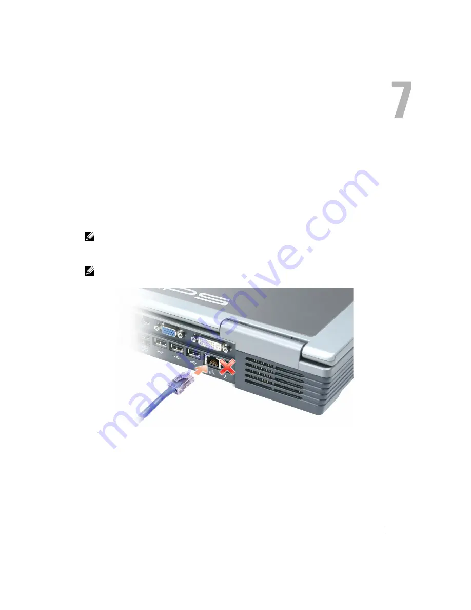
To connect a network cable:

1

Connect the network cable to the network adapter connector on the back of your computer.


NOTE: 

Insert the cable until it clicks into place, and then gently pull it to ensure that it is secure.

2

Connect the other end of the network cable to a network connection device, such as a 
network wall jack.


NOTE: 

Do not use a network cable with a telephone wall jack.

Summary of Contents for Inspiron XPS

Page 1: ...w w w d e l l c o m s u p p o r t d e l l c o m Dell Inspiron XPS Owner s Manual Model PP09L ...

Page 2: ... All rights reserved Reproduction in any manner whatsoever without the written permission of Dell Inc is strictly forbidden Trademarks used in this text Dell the DELL logo TrueMobile Dell TravelLite Inspiron Dell Precision Dimension OptiPlex Latitude PowerEdge PowerVault PowerConnect PowerApp DellNet Axim and Dell OpenManage are trademarks of Dell Inc Intel Pentium and Celeron areregisteredtradema...

Page 3: ...atic Discharge 14 SAFETY Battery Disposal 15 Finding Information 17 1 A Tour of Your Computer Front View 21 Left Side View 25 Right Side View 26 Back View 27 Bottom View 31 2 Using Your Computer Transferring Information to a New Computer 33 Configuring Graphics Cards 34 Settings and Functions 34 Connecting Your Computer to a TV or Audio Device 35 S Video and Standard Audio 36 S Video and S PDIF Di...

Page 4: ...DR Memory and Processor Front Side Bus 47 Hyper Threading 47 4 Using a Battery Battery Performance 49 Checking the Battery Charge 50 Dell QuickSet Battery Meter 50 Microsoft Windows Power Meter 50 Charge Gauge 50 Low Battery Warning 51 Charging the Battery 51 Removing a Battery 52 Installing a Battery 53 Storing a Battery 53 5 Using the Module Bay About the Module Bay 55 Removing and Installing De...

Page 5: ...Track Stick 63 Changing the Track Stick Cap 63 7 Setting Up a Home and Office Network Connecting to a Network Adapter 65 Network Setup Wizard 66 Connecting to a Wireless Local Area Network 66 Determining Your Network Type 66 Connecting to a Wireless Network in Microsoft Windows XP 67 Configuring Security Settings Optional 70 8 Solving Problems Using the Dell Diagnostics 75 When to Use the Dell Dia...

Page 6: ...esponding 88 A solid blue screen appears 88 Error messages appear 88 CD or DVD Problems 89 If you cannot play a CD CD RW or DVD 89 If you cannot eject the CD CD RW or DVD drive tray 89 If you hear an unfamiliar scraping or grinding sound 90 Sound and Speaker Problems 90 If you have a problem with integrated speakers 90 If you have a problem with external speakers 91 E Mail Modem and Internet Probl...

Page 7: ... 103 Recommended Tools 103 Shutting Down Your Computer 103 Memory 105 Mini PCI Card 108 Hard Drive 111 Returning a Hard Drive to Dell 112 Subwoofer 113 Keyboard 114 PC Card With Bluetooth Wireless Technology 116 Modem 117 Removing the Modem 117 Installing the Modem 118 Keyboard Bracket 118 Fans 119 Hinge Covers 121 Display 124 Display Latch 127 Video Card 128 Processor Thermal Cooling Assembly 129...

Page 8: ...r 140 Video Connector 140 S Video TV Out Connector 141 IEEE 1394 Connector 141 DVI I Connector 142 10 Appendix Specifications 143 Using the System Setup Program 149 Overview 149 Viewing the System Setup Screens 150 System Setup Screens 150 Commonly Used Options 150 Enabling the Infrared Sensor 151 Dell Technical Support Policy U S Only 152 Definition of Dell Installed Software and Peripherals 152 ...

Page 9: ... Limited Warranty Terms for Dell Branded Hardware Products Canada Only 174 Dell Software and Peripherals Canada Only 177 1 Year End User Manufacturer Guarantee Latin America and the Caribbean Only 178 Intel Warranty Statement for Pentium and Celeron Processors Only U S and Canada Only 180 Index 183 ...

Page 10: ...10 Contents ...

Page 11: ...esting directly on exposed skin for extended periods of time The surface temperature of the base will rise during normal operation particularly when AC power is present Allowing sustained contact with exposed skin can cause discomfort or eventually a burn Do not use your computer in a wet environment for example near a bath tub sink or swimming pool or in a wet basement If your computer includes a...

Page 12: ... carry a battery pack in your pocket purse or other container where metal objects such as car keys or paper clips could short circuit the battery terminals The resulting excessive current flow can cause extremely high temperatures and may result in damage to the battery pack or cause fire or burns The battery poses a burn hazard if you handle it improperly Do not disassemble it Handle a damaged or...

Page 13: ...able in case you are asked to turn on the computer When traveling with the hard drive removed from the computer wrap the drive in a nonconducting material such as cloth or paper If you have the drive checked by hand be ready to install the drive in the computer You can put the hard drive through an X ray security machine but never put the drive through a metal detector When traveling do not place ...

Page 14: ...e installing a memory module Mini PCI card fan keyboard display reserve battery or PC Card with Bluetooth wireless technology NOTICE Wait 5 seconds after turning off the computer before disconnecting a device or removing a memory module Mini PCI card fan keyboard display reserve battery or PC Card with Bluetooth wireless technology to help prevent possible damage to the system board 1 Shut down yo...

Page 15: ...cell reserve battery For instructions about replacing the lithium ion battery in your computer see Removing a Battery on page 52 and Installing a Battery on page 53 The reserve battery is a long life battery and it is very possible that you will never need to replace it However should you need to replace it see Reserve Battery on page 134 for instructions Do not dispose of the battery along with h...

Page 16: ...16 Safety Instructions w w w d e l l c o m s u p p o r t d e l l c o m ...

Page 17: ... and Utilities CD also known as the ResourceCD Documentation and drivers are already installed on your computer You can use the CD to reinstall drivers see page 94 for instructions run the Dell Diagnostics see page 75 for instructions or access your documentation Readme files may be included on your CD to provide last minute updates about technical changes to your computer or advanced technical re...

Page 18: ...r s guides 3 Click Dell Inspiron Help Service Tag and Express Service Code Microsoft Windows License Label Service Tag and Microsoft Windows License These labels are located on the bottom of your computer Use the Service Tag to identify your computer when you use support dell com or contact technical support Enter the Express Service Code to direct your call when you contact technical support The ...

Page 19: ... and white papers How to use Windows XP Documentation for my computer Documentation for devices such as a modem Windows Help and Support Center 1 Click the Start button and click Help and Support 2 Type a word or phrase that describes your problem and click the arrow icon 3 Click the topic that describes your problem 4 Follow the instructions on the screen How to reinstall my operating system Oper...

Page 20: ...20 Finding Information w w w d e l l c o m s u p p o r t d e l l c o m ...

Page 21: ...ormation about your display see the Dell Inspiron Help file To access the help file see page 18 display latch keyboard display track stick touch pad volume control button track stick touch pad buttons mute button power button display latch release speakers keyboard status lights device status lights media control buttons ...

Page 22: ...omputer is in a power management mode It also flashes to indicate battery charge status Turns on when a PC Card with Bluetooth wireless technology is enabled NOTE The PC Card with Bluetooth wireless technology is an optional feature so the light turns on only if you ordered the card with your computer For more information see the Windows Help and Support Center online documentation on PC Cards wit...

Page 23: ...on supported keyboard shortcuts see Key Combinations on page 59 MEDIA CONTROL BUTTONS Control CD and DVD playback TOUCH PAD Touch pad and touch pad buttons provide the functionality of a mouse DISPLAY LATCH RELEASE Press this to release the display latch and open the display SPEAKERS To adjust the volume of the integrated speakers press the volume control button or speaker volume key combinations ...

Page 24: ... t d e l l c o m KEYBOARD STATUS LIGHTS The green lights located above the keyboard indicate the following Turns on when the numeric keypad is enabled Turns on when the uppercase letter function is enabled Turns on when the scroll lock function is enabled 9 A ...

Page 25: ...tware and data PC CARD SLOT Supports one PC Card such as a modem or network adapter The computer ships with a plastic blank installed in the slot For more information see the Dell Inspiron Help file To access the help file see page 18 IEEE 1394 CONNECTOR Connects devices supporting IEEE 1394 high speed transfer rates such as some digital video cameras audio connectors IEEE 1394 connector PC Card s...

Page 26: ...you attach a commercially available antitheft device to the computer For more information see the instructions included with the device NOTICE Before you buy an antitheft device ensure that it will work with the security cable slot Attach a microphone to the connector Attach headphones or speakers to the connector security cable slot ...

Page 27: ...ter to a TV Also connects digital audio capable devices using the TV digital audio adapter cable S video TV out connector video connector digital video interface connector AC adapter connector USB connectors 3 network connector RJ 45 modem connector RJ 11 D Bay powered USB connector ...

Page 28: ...ormation see the Dell Inspiron Help file To access the help file see page 18 Connect USB devices such as a mouse keyboard or printer You can also connect the optional floppy drive directly to a USB connector using the optional floppy drive cable as shown below Connects an external DVI compatible monitor With an adapter cable you can also connect an external VGA compatible monitor to the DVI connec...

Page 29: ... information on using the modem see the online modem documentation supplied with your computer Connects the computer to a network The green and yellow lights next to the connector indicate activity for both wired and wireless network communications For information on using the network adapter see the online network adapter documentation supplied with your computer Connects powered USB devices such...

Page 30: ...The AC adapter works with electrical outlets worldwide However power connectors and power strips vary among countries Using an incompatible cable or improperly connecting the cable to the power strip or electrical outlet may cause fire or equipment damage NOTICE Do not use an AC adapter rated at less than 150 W with this computer NOTICE When you disconnect the AC adapter cable from the computer gr...

Page 31: ...e 49 BATTERY CHARGE GAUGE Provides information on the battery charge See page 50 FAN The computer uses fans to create airflow through the vents which prevents the computer from overheating See page 119 BATTERY BAY LATCH RELEASE Releases the battery from the battery bay See Removing a Battery on page 52 MEMORY MODULE COVER Covers the compartment that contains the memory modules See page 105 HARD DR...

Page 32: ...32 A Tour of Your Computer w w w d e l l c o m s u p p o r t d e l l c o m ...

Page 33: ...ard 2 When the Files and Settings Transfer Wizard welcome screen appears click Next 3 On the Which computer is this screen click New Computer and click Next 4 On the Do you have a Windows XP CD screen click I will use the wizard from the Windows XP CD and click Next 5 When the Now go to your old computer screen appears go to your source computer Do not click Next at this time To copy data from the...

Page 34: ...ptimal performance with most games and other video programs However some game manufacturers may recommend that you either change a setting or enable or disable a certain function for a game to properly run You may also want to readjust settings to better fit your gaming style Some settings such as Direct3D or OpenGL enable you to adjust the card for higher performance or for higher image quality O...

Page 35: ...o your TV For audio devices without support for S PDIF digital audio you can use the audio connector on the side of the computer to connect the computer to your audio device It is recommended that you connect video and audio cables to your computer in one of the following combinations NOTE See the diagrams at the beginning of each subsection to help you determine which method of connection you sho...

Page 36: ...nect NOTE You can connect an S video cable directly to the S video TV out connector on the computer without the TV digital audio adapter cable if your TV or audio device supports S video but not S PDIF digital audio 2 Connect the TV digital audio adapter cable to the S video TV out connector on your computer TV digital audio adapter cable S video cable standard audio cable ...

Page 37: ...end of the audio cable in to the headphone connector on your computer 6 Plug the two RCA connectors on the other end of the audio cable in to the audio input connectors on your TV or other audio device 7 Turn on the TV and any audio device that you connected and then turn on the computer 8 See Enabling the Display Settings for a TV on page 43 to ensure that the computer recognizes and works proper...

Page 38: ...gital audio adapter cable 4 Plug the other end of the S video cable in to the S video input connector on the TV 5 Plug one end of the S PDIF digital audio cable in to the digital audio connector on the TV digital audio adapter cable 6 Plug the other end of the S PDIF digital audio cable in to the audio input connector on your TV or other audio device 7 Turn on the TV turn on any audio device that ...

Page 39: ...zes and works properly with the TV Composite Video and Standard Audio 1 Turn off the computer and the TV and or audio device that you want to connect 2 Connect the TV digital audio adapter cable to the S video TV out connector on the computer composite video cable TV digital audio adapter cable standard audio cable ...

Page 40: ... Plug the single connector end of the audio cable in to the headphone connector on the computer 6 Plug the two RCA connectors on the other end of the audio cable in to the audio input connectors on your TV or other audio device 7 Turn on the TV turn on any audio device that you connected if applicable and then turn on the computer 8 See Enabling the Display Settings for a TV on page 43 to ensure t...

Page 41: ...f the composite video cable in to the composite video input connector on the TV 5 Plug one end of the S PDIF digital audio cable in to the S PDIF audio connector on the TV digital audio adapter cable 6 Plug the other end of the digital audio cable in to the S PDIF input connector on your TV or other audio device 7 Turn on the TV turn on any audio device that you connected if applicable and then tu...

Page 42: ... Enabling S PDIF in the Windows Audio Driver NOTE Enabling S PDIF in Windows disables the sound from the headphone connector 1 Double click the speaker icon in the Windows notification area 2 Click the Options menu and then click Advanced Controls 3 Click Advanced 4 Click Enable S PDIF 5 Click Close 6 Click OK Setting Up the Dolby Headphone NOTE The Dolby headphone feature is available only if you...

Page 43: ...eft corner of the TV button to enable the TV 7 Click OK Connecting Monitors NOTE If you are connecting two monitors that both have VGA connectors you must have the optional VGA adapter available from Dell If you are connecting two flat panel monitors at least one of them must have a VGA connector If you are connecting a television you may connect only one monitor VGA or DVI in addition to the tele...

Page 44: ...ct the VGA connector on the monitor to the VGA blue connector on the computer b Connect the DVI connector on the other monitor to the DVI white connector on the computer NOTE To connect a television to your computer you must use the S video cable included with your computer If you are connecting two monitors and one of the monitors is a television a Connect one end of the S video cable to the TV o...

Page 45: ...r purposes including creating CDs from audio files on your computer and creating MP3 CDs For instructions see the Sonic RecordNow documentation that came with your computer Open Sonic RecordNow click the question mark icon in the upper right corner of the window and then click RecordNow Help or RecordNow Tutorial How to Copy a CD or DVD NOTE If you have a DVD CD RW combo drive and you experience r...

Page 46: ...s CD RWs including High Speed CD RWs DVD Rs and DVD RWs Blank DVD Rs can be used to permanently store large amounts of information After creating a DVD R disc you may not be able write to that disc again depending on whether or not the disc is finalized or closed the final stage of the disc creation process Use blank DVD RWs when you will need to erase rewrite or update the information on that dis...

Page 47: ...modules installed and they must be of the same memory capacity For information on installing memory see page 105 For more information on the type of memory supported by your computer see page 144 Hyper Threading Hyper Threading is an Intel technology that can enhance overall computer performance by allowing one physical processor to function as two logical processors capable of performing certain ...

Page 48: ...48 Optimizing Performance w w w d e l l c o m s u p p o r t d e l l c o m ...

Page 49: ... DVD RW and CD RW drives Using wireless communications devices PC Cards or USB devices Using high brightness display settings 3D screen savers or other power intensive programs such as 3D games Running the computer in maximum performance mode See Power Management in the Dell Inspiron Help file for more information To access the help file see page 18 NOTE It is recommended that you connect your com...

Page 50: ...r window For more information about QuickSet right click the icon in the taskbar and click Help Microsoft Windows Power Meter The Windows Power Meter indicates the remaining battery charge To check the Power Meter double click the icon on the taskbar For more information about the Power Meter tab see Power Management in the Dell Inspiron Help file To access the help file see page 18 If the compute...

Page 51: ...as you like The battery s internal circuitry prevents the battery from overcharging When you connect the computer to an electrical outlet or install a battery while the computer is connected to an electrical outlet the computer checks the battery charge and temperature If necessary the AC adapter then charges the battery and maintains the battery charge If the battery is hot from being used in you...

Page 52: ...y CAUTION Before performing these procedures disconnect all cables from the computer 1 Ensure that the computer is turned off or disconnected from an electrical outlet 2 Slide and hold the battery bay latch release on the bottom of the computer and then remove the battery from the bay ...

Page 53: ...gree angle 2 Press the other side down until the latch release clicks Storing a Battery Remove the battery when you store your computer for an extended period of time A battery discharges during prolonged storage After a long storage period recharge the battery fully before you use it ...

Page 54: ...54 Using a Battery w w w d e l l c o m s u p p o r t d e l l c o m ...

Page 55: ...VD RW or second hard drive in the module bay Your Dell Inspiron computer ships with a CD DVD or other optical drive installed in the module bay Removing and Installing Devices While the Computer Is Turned Off NOTICE To prevent damage to devices store them in a safe dry place when they are not installed in the computer Avoid pressing down on them or placing heavy objects on top of them 1 Press the ...

Page 56: ...ices While the Computer Is Running 1 Before ejecting the device double click the Safely Remove Hardware icon on the taskbar click the device you want to eject and click Stop NOTICE To prevent damage to devices store them in a safe dry place when they are not installed in the computer Avoid pressing down on them or placing heavy objects on top of them device latch release module bay device ...

Page 57: ...ll the device out of the module bay 4 Push the new device into the bay until it clicks The operating system automatically recognizes the device 5 If necessary enter your password to unlock your computer device latch release device latch release module bay device ...

Page 58: ...58 Using the Module Bay w w w d e l l c o m s u p p o r t d e l l c o m ...

Page 59: ...r or symbol hold down Fn and press the desired key To enable the keypad press Num Lk The light indicates that the keypad is active To disable the keypad press Num Lk again Key Combinations System Functions Battery CD or DVD Tray Ctrl Shift Esc Opens the Task Manager window Num Lk Enables and disables the numeric keypad Fn Num Lk Enables and disables the scroll lock function Fn F3 Displays the Dell...

Page 60: ...Fn F2 Enables and disables radios including wireless networking and the PC Card with Bluetooth wireless technology Fn Esc Activates a power management mode You can reprogram this keyboard shortcut to activate a different power management mode using the Advanced tab in the Power Options Properties window For instructions see Power Management in the Dell Inspiron Help file To access the help file se...

Page 61: ...go key and m Minimizes all open windows Windows logo key and Shift m Maximizes all windows Windows logo key and e Runs Windows Explorer Windows logo key and r Opens the Run dialog box Windows logo key and f Opens the Search Results dialog box Windows logo key and Ctrl f Opens the Search Results Computer dialog box if the computer is connected to a network Windows logo key and Pause Opens the Syste...

Page 62: ...he left touch pad button To select and move or drag an object position the cursor on the object and tap down up down on the touch pad On the second down motion leave your finger on the touch pad and move the selected object by sliding your finger over the surface To double click an object position the cursor on the object and tap twice on the touch pad or use your thumb to press the left touch pad...

Page 63: ... to adjust touch pad and track stick settings 3 Select the desired settings and click Apply 4 Click OK to save the settings and close the window Changing the Track Stick Cap You can replace your track stick cap if it wears down from prolonged use You can purchase additional caps by visiting the Dell website at www dell com 1 Pull the cap off the track stick 2 Align the new cap over the square trac...

Page 64: ...64 Using the Keyboard and Touch Pad w w w d e l l c o m s u p p o r t d e l l c o m ...

Page 65: ...a network cable connected to it To connect a network cable 1 Connect the network cable to the network adapter connector on the back of your computer NOTE Insert the cable until it clicks into place and then gently pull it to ensure that it is secure 2 Connect the other end of the network cable to a network connection device such as a network wall jack NOTE Do not use a network cable with a telepho...

Page 66: ...d preparations 5 Return to the Network Setup Wizard and follow the instructions on the screen Connecting to a Wireless Local Area Network NOTE These networking instructions do not apply to PC Cards with Bluetooth wireless technology or cellular products Determining Your Network Type NOTE Most wireless networks are of the infrastructure type Wireless networks fall into three categories infrastructu...

Page 67: ...s Guides Network User s Guides category The user s guide is also available on the Dell Support website at support dell com 1 Click the Start button click Control Panel and then click Switch to Classic View 2 Double click Network Connections 3 Click Wireless Network Connection The Wireless Network Connection icon is highlighted 4 Under Network Tasks in the left hand pane click Change settings of th...

Page 68: ...68 Setting Up a Home and Office Network w w w d e l l c o m s u p p o r t d e l l c o m 6 Click Add The Wireless network properties window appears ...

Page 69: ...option to select WPA download the WPA wireless security update from the Microsoft support site 7 Enter the name of your network in the Network name SSID field 8 If you do not need to configure security settings go to step 9 If you choose to configure security settings optional go to Configuring Security Settings Optional on page 70 ...

Page 70: ...ons based on the security settings for your network Connecting to a Network with Wired Equivalent Protocol WEP Security Requirements Connecting to a Network with Wi Fi Protected Access WPA Security Requirements NOTE Network security settings are unique to your network Dell cannot provide this information Connecting to a Network With Wired Equivalent Protocol WEP Security Requirements 1 In the Pref...

Page 71: ...heck box and go to step 5 4 From the Data encryption drop down menu select WEP 5 If the wireless network does not require a network key such as a password go to step 9 6 Click to uncheck the The key is provided for me automatically check box 7 Enter the WEP network key in the Network key field 8 Enter the WEP network key again in the Confirm network key field NOTE Your computer can take up to 1 mi...

Page 72: ...otocols require that you know the network authentication and data encryption settings for your wireless network In addition your WPA protected network may require special settings such as a network key user name password and domain name 1 In the Preferred networks field click the name of your wireless network 2 Click Properties 3 From the Network Authentication drop down menu select your network a...

Page 73: ... Data encryption drop down menu select your data encryption type 5 If your wireless network requires a key enter it in the Network key field NOTE Your computer can take up to 1 minute to connect to the network 6 Click OK Your network setup is complete ...

Page 74: ...74 Setting Up a Home and Office Network w w w d e l l c o m s u p p o r t d e l l c o m ...

Page 75: ... cannot see anything on your display hold down the mute button and press the computer s power button to begin the Dell Diagnostics The computer automatically runs the Pre boot System Assessment NOTE If you see a message stating that no diagnostics utility partition has been found run the Dell Diagnostics from your Drivers and Utilities CD If you wait too long and the Microsoft Windows logo appears...

Page 76: ...age appears with an error code and a description of the problem Write down the error code and problem description and follow the instructions on the screen If you cannot resolve the error condition contact Dell see Contacting Dell on page 152 NOTE The Service Tag for your computer is located at the top of each test screen If you contact Dell a technical support representative will ask for your Ser...

Page 77: ...ration Displays your hardware configuration for the selected device The Dell Diagnostics obtains configuration information for all devices from the system setup program memory and various internal tests and it displays the information in the device list in the left pane of the screen The device list may not display the names of all the components installed on your computer or all devices attached ...

Page 78: ...x i386 ntdlr c 6 The message 1 file s copied appears 7 Type copy x i386 ntdetect com c where x is the drive letter of your CD drive 8 The message 1 file s copied appears 9 Remove the Operating System CD and press Ctrl Alt Del to shut down and then restart the computer NOT ENOUGH MEMORY OR RESOURCES EXIT SOME PROGRAMS AND TRY AGAIN You have too many programs open Close all windows and open the prog...

Page 79: ...ing a battery to power your computer the battery charge may be depleted Connect the computer to an electrical outlet using the AC adapter and turn on the computer TEST THE ELECTRICAL OUTLET Ensure that the electrical outlet is working by testing it with another device such as a lamp CHECK THE AC ADAPTER Check the AC adapter cable connections If the AC adapter has a light ensure that it is on CONNE...

Page 80: ...amps or other appliances ROTATE THE COMPUTER TO FACE A DIFFERENT DIRECTION Eliminate sunlight glare which can cause poor picture quality ADJUST THE WINDOWS DISPLAY SETTINGS 1 Click the Start button and then click Control Panel 2 Click Appearance and Themes 3 Click the area you want to change or click the Display icon 4 Try different settings for Color quality and Screen resolution SEE ERROR MESSAG...

Page 81: ...ly connected to the computer and to the scanner UNLOCK THE SCANNER Ensure that your scanner is unlocked if it has a locking tab or button REINSTALL THE SCANNER DRIVER See the scanner documentation for instructions ALLOW THE COMPUTER TO COOL BEFORE TURNING IT ON A hot hard drive may prevent the operating system from starting Try allowing the computer to return to room temperature before turning it ...

Page 82: ...D NOT PROVIDED BY DELL Contact the PC Card manufacturer CHECK THE KEYBOARD CABLE Shut down the computer see page 103 Disconnect the keyboard cable and check it for damage If you are using a keyboard extension cable disconnect it and connect the keyboard directly to the computer CHECK THE EXTERNAL KEYBOARD 1 Turn off the computer wait 1 minute and turn it on again 2 Verify that the numbers capitals...

Page 83: ...s blinking the computer is in standby mode press the power button to exit standby mode If the light is off press the power button to turn on the computer CHARGE THE BATTERY The battery charge may be depleted 1 Reinstall the battery 2 Use the AC adapter to connect the computer to an electrical outlet 3 Turn on the computer CHECK THE BATTERY STATUS LIGHT If the battery status light flashes orange or...

Page 84: ...andby in the Windows Help and Support Center To access help see page 18 RESEAT THE MEMORY MODULES If the computer power light turns on but the display remains blank reseat the memory modules For instructions see Memory on page 105 DISABLE THE NUMERIC KEYPAD Press Fn Num Lk to disable the numeric keypad if numbers are displayed instead of letters Verify that the numbers lock light is not lit CHECK ...

Page 85: ...r cable is properly connected to the computer TEST THE ELECTRICAL OUTLET Ensure that the electrical outlet is working by testing it with another device such as a lamp ENSURE THAT THE PRINTER IS TURNED ON See the documentation supplied with the printer VERIFY THAT WINDOWS RECOGNIZES THE PRINTER 1 Click the Start button 2 Click Control Panel 3 Click Printers and Other Hardware 4 Click View installed...

Page 86: ...odem and connect it to a telephone Listen for a dial tone Ensure that you have touchtone telephone service Try connecting the modem to a different telephone wall jack Slow connection speeds can be caused by telephone noise as well as by telephone line or network conditions Contact your telephone company or network administrator for more information CONNECT THE MODEM CABLE DIRECTLY TO THE TELEPHONE...

Page 87: ...lick Printers and Other Hardware and click Phone and Modem Options 3 Click the Modems tab 4 Click the COM port for your modem 5 Click Properties click the Diagnostics tab and then click Query Modem to verify that the modem is communicating with Windows If all commands receive responses the modem is operating properly CHECK THE NETWORK CABLE CONNECTOR Ensure that the network cable connector is firm...

Page 88: ...nstall the program if necessary END THE PROGRAM 1 Simultaneously press Ctrl Shift Esc 2 Click the Applications tab and then select the program that is no longer responding 3 Click End Task TURN THE COMPUTER OFF If the computer does not respond to a keystroke or a proper shutdown see page 103 press the power button until the computer turns off Press the power button again to restart the computer Th...

Page 89: ...he light is blinking indicating normal operation TRY ANOTHER DISC Insert another disc to eliminate the possibility that the original disc is defective ADJUST THE WINDOWS VOLUME CONTROL Double click the speaker icon in the lower right corner of your screen Ensure that the volume is turned up and that the sound is not muted REINSTALL THE DRIVE 1 Save and close any open files exit any open programs a...

Page 90: ...ows Help and Support Center To access the Help and Support Center see page 19 CHANGE THE WRITE SPEED TO A SLOWER RATE See the help files for your CD creation software EXIT ALL OTHER OPEN PROGRAMS Exiting all other open programs before writing to the CD RW may alleviate the problem ADJUST THE WINDOWS VOLUME CONTROL Double click the speaker icon in the lower right corner of your screen Ensure that t...

Page 91: ... ADJUST THE WINDOWS VOLUME CONTROL Double click the speaker icon in the lower right corner of your screen Ensure that the volume is turned up and that the sound is not muted Adjust the volume bass or treble controls to eliminate distortion TEST THE SPEAKERS Plug the speaker audio cable into the line out connector on the computer Ensure that the headphone volume control is turned up Play a music CD...

Page 92: ...when you insert the telephone line connector into the modem Disconnect the telephone line from the modem and connect it to a telephone Listen for a dial tone If you have other telephone devices sharing the line such as an answering machine fax machine surge protector or line splitter then bypass them and use the telephone to connect the modem directly to the telephone wall jack If you are using a ...

Page 93: ... problems connecting to the Internet your computer might be infected with spyware Use an anti virus program that includes anti spyware protection your program may require an upgrade to scan the computer and remove spyware For more information go to support dell com and search for the keyword spyware GO TO THE DELL SUPPORT WEBSITE Go to support dell com for help with general usage installation and ...

Page 94: ...ice Manager 6 Scroll down the list to see if any device has an exclamation point a yellow circle with a on the device icon If an exclamation point is next to the device name you may need to reinstall the driver or install a new driver as described in the following section Reinstalling Drivers and Utilities NOTICE The Dell Support website at support dell com and your Drivers and Utilities CD provid...

Page 95: ... driver or utility if available A welcome screen appears 4 Click Next The CD automatically scans your hardware to detect drivers and utilities used by your computer 5 After the CD completes the hardware scan you can also detect other drivers and utilities Under Search Criteria select the appropriate categories from the System Model Operating System and Topic drop down menus A link or links appear ...

Page 96: ...n the name of the appropriate driver appears click Next 10 Click Finish and restart your computer Resolving Software and Hardware Incompatibilities If a device is either not detected during the operating system setup or is detected but incorrectly configured you can use Device Manager or the Hardware Troubleshooter to resolve the incompatibility To resolve incompatibilities using Device Manager 1 ...

Page 97: ...Click the Start button and click Help and Support 2 Click System Restore 3 Follow the instructions on the screen Restoring the Computer to an Earlier Operating State If problems occur after you install a device driver use Device Driver Rollback see page 94 to resolve the problem If that is unsuccessful then use System Restore NOTICE Before you restore the computer to an earlier operating state sav...

Page 98: ...and click Next 3 Click Next The System Restore screen appears and the computer restarts 4 After the computer restarts click OK Enabling System Restore If you reinstall Windows XP with less than 200 MB of free hard disk space available System Restore is automatically disabled To see if System Restore is enabled 1 Click the Start button and click Control Panel 2 Click Performance and Maintenance 3 C...

Page 99: ...s XP The options can overwrite files and possibly affect programs installed on your hard drive Therefore do not reinstall Windows XP unless a Dell technical support representative instructs you to do so NOTICE To prevent conflicts with Windows XP disable any virus protection software installed on your computer before you reinstall Windows XP See the documentation that came with the software for in...

Page 100: ... name for your computer or accept the name provided and click Next If you are reinstalling Windows XP Professional at the Computer Name and Administrator Password window enter a name for your computer or accept the one provided and a password and click Next 9 If the Modem Dialing Information screen appears enter the requested information and click Next 10 Enter the date time and time zone in the D...

Page 101: ... Utilities CD For instructions see Reinstalling Drivers and Utilities on page 94 20 Reinstall your virus protection software 21 Reinstall your programs NOTE To reinstall and activate your Microsoft Office or Microsoft Works Suite programs you need the Product Key number located on the back of the Microsoft Office or Microsoft Works Suite CD sleeve ...

Page 102: ...102 Solving Problems w w w d e l l c o m s u p p o r t d e l l c o m ...

Page 103: ...ential damage and to help ensure your own personal safety CAUTION Before you begin this procedure read the safety instructions at the front of this document see page 11 CAUTION Handle components and cards with care Do not touch the components or contacts on a card Hold a card by its edges or by its metal mounting bracket Hold a component such as a memory module by its side edges not by its connect...

Page 104: ...rst unplug the cable from your computer and then unplug it from the network wall jack 4 Disconnect any telephone or telecommunication lines from the computer 5 Disconnect your computer and all attached devices from their electrical outlets and then press the power button to ground the system board NOTICE To connect a network cable first plug the cable into the network wall jack and then plug it in...

Page 105: ... this procedure read the safety instructions at the front of this document see page 11 NOTICE To avoid damaging the system board you must remove the main battery before you begin working inside the computer see page 52 NOTE Memory modules purchased from Dell are covered under your computer warranty NOTE This computer requires matched memory modules and therefore always has two identical memory mod...

Page 106: ...ee angle NOTICE Ensure that memory modules are installed in both connectors and they are of the same capacity Insert memory modules at a 45 degree angle to avoid damaging the connector 4 Ground yourself and install the new memory module NOTE If the memory module is not installed properly the computer may not boot properly No error message indicates this failure a Align the notch in the module edge...

Page 107: ...er 6 Insert the battery into the battery bay or connect the AC adapter to your computer and an electrical outlet 7 Turn on the computer As the computer boots it detects the additional memory and automatically updates the system configuration information To confirm the amount of memory installed in the computer click the Start button click Help and Support and then click Computer Information ...

Page 108: ...s approved for use in your portable computer may be installed Approved Mini PCI cards may be purchased only from Dell CAUTION Before you begin this procedure read the safety instructions at the front of this document see page 11 NOTICE To avoid damaging the system board you must remove the main battery before you begin working inside the computer see page 52 NOTE 2 4 GHz Wireless LAN PC Cards may ...

Page 109: ...f you are replacing a Mini PCI card first remove the existing card a Disconnect the antenna cables from the Mini PCI card b Release the Mini PCI card by spreading the metal securing tabs until the card pops up slightly c Lift the Mini PCI card out of its connector antenna cables securing tabs ...

Page 110: ... realign the card 5 To install a Mini PCI card align the card with the connector at a 45 degree angle and press the card into the connector until it clicks NOTICE To avoid damaging the antenna cables or the Mini PCI card never place the cables under the card 6 Connect the antenna cables to the Mini PCI card 7 Replace the Mini PCI card cover and tighten the captive screw antenna cables ...

Page 111: ... hard drive Do not remove the hard drive while the computer is on in standby mode or in hibernate mode NOTICE Hard drives are extremely fragile even a slight bump can damage the drive NOTE Dell does not guarantee compatibility or provide support for hard drives from sources other than Dell NOTE You need the Operating System CD to install the Microsoft Windows operating system You also need the Dri...

Page 112: ... place If you use excessive force you may damage the connector 5 Slide the drive into the bay until it is fully seated 6 Replace and tighten the screw 7 Use the Operating System CD to install the operating system for your computer For instructions see Reinstalling Microsoft Windows XP on page 98 8 Use the Drivers and Utilities CD to install the drivers and utilities for your computer For instructi...

Page 113: ... back panel of the computer If you ordered a subwoofer with your computer it is already installed To remove and replace a subwoofer 1 Follow the procedures in Before You Begin see page 103 2 Remove the battery see page 52 3 Remove the subwoofer from the battery a Disconnect the subwoofer cable b Apply a small screwdriver or scribe to the notch in the side of the battery releasing the subwoofer fro...

Page 114: ...ont of this document see page 11 NOTICE To avoid electrostatic discharge ground yourself by using a wrist grounding strap or by periodically touching a connector on the back panel of the computer NOTICE To avoid damaging the system board you must remove the main battery before you begin working inside the computer 1 Follow the procedures in Before You Begin see page 103 2 Remove the center hinge c...

Page 115: ...ard and gently slide it toward the display c Hold the keyboard up and slightly forward to allow access to the keyboard connector d Pull up on the keyboard connector tab to disconnect the keyboard connector from the system board NOTICE To avoid scratching the palm rest when replacing the keyboard hook the four tabs along the front edge of the keyboard into the palm rest and then secure the keyboard...

Page 116: ...g a connector on the back panel of the computer NOTICE To avoid damaging the system board you must remove the main battery before you begin working inside the computer If you ordered a PC Card with Bluetooth wireless technology with your computer it is already installed 1 Remove the battery see page 52 2 Open the card door 3 Using a plastic scribe or screwdriver gently pry the module from the plas...

Page 117: ...nnector on the back panel of the computer Removing the Modem 1 Follow the procedures in Before You Begin see page 103 2 Remove the center hinge cover see page 121 3 Remove the keyboard see page 114 4 Remove the M2 x 3 mm screw 5 Pull up on the pull tab to disconnect the modem from the modem connector on the system board NOTICE Do not disconnect the modem cable from the system board 6 Disconnect th...

Page 118: ...his procedure read the safety instructions at the front of this document see page 11 NOTICE To avoid electrostatic discharge ground yourself by using a wrist grounding strap or by periodically touching a connector on the back panel of the computer 1 Follow the procedures in Before You Begin see page 103 2 Remove the center hinge cover see page 121 3 Remove the keyboard see page 114 4 Remove the di...

Page 119: ...ing the system board you must remove the main battery before you begin working inside the computer The two fans are located on the bottom of the computer one with screws labeled F2 fan 2 and one with screws labeled F3 fan 3 To remove fan 2 1 Follow the procedures in Before You Begin see page 103 2 Turn the computer over 3 Unscrew the two captive screws labeled F2 lift up the fan cover and remove i...

Page 120: ...e screw on the fan and lift up the fan release lever 5 Use the fan release lever to lift the fan out of the computer When replacing fan 2 press down on the fan surface labeled Press here to securely seat the fan in place fan cover captive screws 2 audio connectors fan fan release lever screw ...

Page 121: ...sing a wrist grounding strap or by periodically touching a connector on the back panel of the computer NOTICE To avoid damaging the system board you must remove the main battery before you begin working inside the computer 1 Follow the procedures in Before You Begin see page 103 NOTE The hinge cover consists of three separate pieces the left cover the right cover and the center cover To remove com...

Page 122: ...ft the center hinge cover on both sides simultaneously b Slide the left and right hinge covers toward the back of the computer and then slide them to the side away from the computer 3 Remove the center hinge cover a Close the display b Facing the front of the computer press in on the two hinge cover snaps and pull them up slightly to disengage them left hinge cover right hinge cover ...

Page 123: ...k surface d Lift the center hinge cover on the right side first just enough to access the flex cable connector e Using the pull tab disconnect the center hinge cover flex cable from the system board connector hinge cover snaps 2 system board connector center hinge cover flex cable and pull tab center hinge cover ...

Page 124: ...To avoid damaging the system board you must remove the main battery before you begin working inside the computer 1 Follow the procedures in Before You Begin see page 103 NOTICE Before turning the computer over and removing the screws ensure that the display is firmly latched closed 2 Turn the computer over and remove the four screws two on each side labeled D on the bottom of the computer 3 Turn t...

Page 125: ...Adding and Replacing Parts 125 6 Disconnect the display cable using the pull tab 7 Lift the display out of the computer at a 90 degree angle display cable system board connector antenna cables 2 display ...

Page 126: ...place the display ensure that the ribbon tape around the display cable is securely tucked underneath the two tabs Also ensure that the antenna cables are not twisted and that they are lying flat in the antenna cable clip display ribbon tape tabs 2 display antenna cables 2 antenna cable clip ...

Page 127: ...ector on the back panel of the computer NOTICE To avoid damaging the system board you must remove the main battery before you begin working inside the computer 1 Follow the procedures in Before You Begin see page 103 2 Remove the display see page 124 3 Remove the eight rubber display bumpers 4 Remove the two M2 5 x 6 mm shoulder screws and six M2 5 x 6 mm screws and remove the display bezel displa...

Page 128: ...NOTICE To avoid electrostatic discharge ground yourself by using a wrist grounding strap or by periodically touching a connector on the back panel of the computer 1 Follow the procedures in Before You Begin see page 103 2 Remove the center hinge cover see page 121 3 Remove the keyboard see page 114 4 Remove the display see page 124 5 Remove the keyboard bracket see page 118 6 Remove the four M2 5 ...

Page 129: ...by periodically touching a connector on the back panel of the computer Removing the Processor Thermal Cooling Assembly 1 Follow the procedures in Before You Begin see page 103 2 Remove the center hinge cover see page 121 3 Remove the keyboard see page 114 4 Remove the display see page 124 5 Remove the keyboard bracket see page 118 6 Remove the video card see page 128 7 Loosen in consecutive order ...

Page 130: ...is procedure read the safety instructions at the front of this document see page 11 NOTICE To avoid electrostatic discharge ground yourself by using a wrist grounding strap or by periodically touching a connector on the back panel of the computer 1 Follow the procedures in Before You Begin see page 103 2 Remove the center hinge cover see page 121 3 Remove the keyboard see page 114 4 Remove the dis...

Page 131: ...e up and remove the four M2 5 x 3 mm screws labeled circle P 8 Disconnect the touch pad connector from the system board 9 Slide the palm rest forward and remove it from the computer M2 5 x 8 mm screws labeled circle P 3 M2 5 x 3 mm screws 4 touch pad connector ...

Page 132: ...E To avoid damage to the processor hold the screwdriver so that it is perpendicular to the processor when turning the cam screw 1 Follow the instructions in Before You Begin on page 103 2 Remove the video card see page 128 3 Remove the keyboard see page 114 4 Remove the fan see page 119 NOTICE To help ensure maximum cooling for the processor do not touch the heat transfer areas on the processor th...

Page 133: ...dule Seating the processor module properly in the ZIF socket does not require force NOTICE A processor module that is not properly seated can result in an intermittent connection or permanent damage to the processor and ZIF socket 1 Align the pin 1 corner of the processor module with the pin 1 corner of the ZIF socket and insert the processor module NOTE The pin 1 corner of the processor module ha...

Page 134: ...ction Flashing the BIOS 1 Ensure that the AC adapter is plugged in and that the main battery is installed properly 2 Insert the flash BIOS update program floppy disk or CD and turn on the computer Follow the instructions that appear on the screen The computer continues to boot and updates the new BIOS When the update is complete the computer will automatically reboot 3 Press F2 during POST to ente...

Page 135: ...attery clip slightly to disengage it from the fan chassis 6 Pull the reserve battery together with the clip straight out of the computer base NOTE Use a scribe to press the reserve battery cable connector into the system board connector when replacing the reserve battery System Board Removing the System Board CAUTION Before you begin this procedure read the safety instructions at the front of this...

Page 136: ...eplacement system board NOTICE Disconnect the computer and any attached devices from electrical outlets and remove any installed batteries 1 Remove the keyboard see page 114 2 Remove the display see page 124 3 Remove the palm rest see page 130 4 Remove the video card see page 128 5 Remove the processor thermal cooling assembly see page 129 6 Remove the processor see page 132 7 Turn the system over...

Page 137: ...System Board on page 135 in reverse order NOTICE Before turning on the computer replace all screws and ensure that no stray screws remain inside the computer Failure to do so may result in damage to the computer 2 Turn on the computer NOTE After replacing the system board you must enter the computer Service Tag sequence into the BIOS of the replacement system board as part of the BIOS update proce...

Page 138: ... back panel of the computer 1 Follow the procedures in Before You Begin see page 103 2 Remove the center hinge cover see page 121 3 Remove the keyboard see page 114 4 Remove the display see page 124 5 Remove the palm rest see page 130 6 Remove the keyboard bracket see page 118 NOTICE Handle the speakers with care to avoid damaging them 7 Remove the three M2 5 x 5 mm screws from the speakers 8 Lift...

Page 139: ...eriodically touching a connector on the back panel of the computer 1 Remove the hard drive see page 105 2 Remove the keyboard see page 114 3 Remove the display see page 124 4 Remove the palm rest see page 130 5 Remove the system board see page 135 6 Remove the speakers see page 138 7 Remove the two M2 5x 6 mm screws on each side of the latch 8 Pull the latch straight up and away from the computer ...

Page 140: ... d e l l c o m Pin Assignments for I O Connectors USB Connector Video Connector Pin Signal 1 USB5V 2 USBP 3 USBP 4 GND Pin Signal Pin Signal 1 CRT_R 9 5V 2 CRT_G 10 GND 3 CRT_B 11 MONITOR_DETECT 4 NC 12 DDC_DATA 5 GND 13 CRT_HS 6 GND 14 CRT_VS 7 GND 15 DDC_CLK 8 GND ...

Page 141: ...ng and Replacing Parts 141 S Video TV Out Connector IEEE 1394 Connector S Video Pin Signal 1 GND 2 GND 3 DLUMA L 4 DCRMA L Composite Video Pin Signal 5 NC 6 DCMPS L 7 GND Pin Signal 1 TPB 2 TPB 3 TPA 4 TPA ...

Page 142: ... FOR 5V 4 TMDS DATA4 16 HOT PLUG DETECT 5 TMDS DATA4 17 TMDS DATA0 6 DDC CLK 18 TMDS DATA0 7 DDC DATA 19 TMDS DATA0 5 SHLD 8 ANALOG VERT SYNC 20 TMDS DATA5 9 TMDS DATA1 21 TMDS DATA5 10 TMDS DATA1 22 TMDS CLK SHLD 11 TMDS DATA1 3 SHLD 23 TMDS CLK 12 TMDS DATA3 24 TMDS CLK Pin Signal C1 ANALOG RED VID OUT C2 ANALOG GRN VID OUT C3 ANALOG BLU VID OUT C4 ANALOG HOR SYNC C5 ANALOG COM GND RET ...

Page 143: ...n System chip set Intel 865PE Data bus width 64 bits DRAM bus width dual channel DDR memory 64 bits per channel Processor address bus width 32 bits Flash EPROM 1 MB Graphics bus 64 bits PCI bus 32 bits PC Card CardBus controller Texas Instruments PCI 4510 PC Card connector one supports one Type I or Type II card Cards supported 3 3 V and 5 V PC Card connector size 68 pins Data width maximum PCMCIA...

Page 144: ...y 256 MB Maximum memory 2048 MB Ports and Connectors Video 15 hole connector Digital video interface DVI I one 24 hole connector Audio microphone miniconnector stereo headphone speakers miniconnector S PDIF connector USB three 4 pin USB 2 0 compliant connectors D Bay powered USB connector 4 pin power supply IEEE 1394 4 pin mini nonpowered connector Infrared sensor compatible with IrDA Standard 1 1...

Page 145: ...d composite modes Audio Audio type compatible with Soundblaster and Microsoft Windows Sound System Audio controller Intel AC 97 Stereo conversion 20 bit stereo digital to analog 18 bit stereo analog to digital Interfaces Internal AC 97 External microphone miniconnector stereo headphones speakers miniconnector S PDIF connector Speaker two 4 ohm speakers Internal speaker amplifier 2 W per channel st...

Page 146: ... 1280 x 800 WXGA Response time typical 20 ms rise maximum 35 ms fall maximum Refresh rate 60 Hz Operating angle 0 closed to 180 Viewing angles Horizontal 55 Vertical 48 Pixel pitch 0 1725 mm WUXGA 0 1971 mm WSXGA 0 2588 mm WXGA Power Consumption Panel with backlight typical 7 0 W WUXGA 6 0 W WSXGA 5 5 W WXGA Controls brightness can be controlled through key combinations Keyboard Number of keys 87 ...

Page 147: ...dual 8 cell 66 WHr smart lithium ion Dimensions Depth 88 5 mm 3 5 inches Height 21 5 mm 0 8 inch Width 139 0 mm 5 5 inches Weight 12 cell 0 6 kg 1 4 lb dual 8 cell 0 95 kg 2 1 lb Voltage 14 8 VDC Charge time approximate Computer on 2 5 hours Computer off 1 5 hours Operating time Battery operating time varies depending on operating conditions and can be significantly reduced under certain power int...

Page 148: ... power 150 W NOTICE Do not use an AC adapter rated at less than 150 W with this computer Rated output voltage 19 5 VDC Dimensions Height 40 0 mm 1 6 inches Width 85 0 mm 3 4 inches Depth 170 0 mm 6 7 inches Weight with cables 0 68 1 09 kg 1 5 2 4 lb Temperature range Operating 0 to 40 C 32 to 104 F Storage 40 to 70 C 40 to 158 F Physical Height 50 6 mm 1 9 inches Width 358 9 mm 14 1 inches Depth 3...

Page 149: ... System configuration Boot order Boot start up configuration Basic device configuration settings System security and hard drive password settings Environmental Temperature range Operating 0 to 35 C 32 to 95 F Storage 40 to 65 C 40 to 149 F Relative humidity maximum Operating 10 to 90 noncondensing Storage 5 to 95 noncondensing Maximum vibration using a random vibration spectrum that simulates user...

Page 150: ...pear less bright The upper right corner of the screen displays help information for the currently highlighted option the lower right corner displays information about the computer System setup key functions are listed across the bottom of the screen Commonly Used Options Certain options require that you reboot the computer for new settings to take effect Changing the Boot Sequence The boot sequenc...

Page 151: ...go appears continue to wait until you see the Windows desktop Then shut down your computer and try again 4 When the boot device list appears highlight the device from which you want to boot and press Enter The computer boots to the selected device The next time you reboot the computer the previous boot order is restored Enabling the Infrared Sensor 1 Enter the system setup program a Turn on your c...

Page 152: ...roject are covered by the stan dard Dell limited warranty for your computer However Dell also extends a parts replacement program to cover all nonstandard third party hardware components integrated through CFI for the duration of the com puter s service contract Definition of Dell Installed Software and Peripherals Dell installed software includes the operating system and some of the software prog...

Page 153: ...oll free 800 335 0031 Antigua and Barbuda General Support 1 800 805 5924 Argentina Buenos Aires International Access Code 00 Country Code 54 City Code 11 Website www dell com ar Tech Support and Customer Care toll free 0 800 444 0733 Sales 0 810 444 3355 Tech Support Fax 11 4515 7139 Customer Care Fax 11 4515 7138 Aruba General Support toll free 800 1578 Australia Sydney International Access Code ...

Page 154: ...E mail tech_be dell com E mail for French Speaking Customers support euro dell com be fr emaildell Technical Support 02 481 92 88 Customer Care 02 481 91 19 Corporate Sales 02 481 91 00 Fax 02 481 92 99 Switchboard 02 481 91 00 Bermuda General Support 1 800 342 0671 Bolivia General Support toll free 800 10 0238 Brazil International Access Code 00 Country Code 55 City Code 51 Website www dell com b...

Page 155: ...ll free 1 800 847 4096 Technical Support med large bus government toll free 1 800 387 5757 Sales Home Sales Small Business toll free 1 800 387 5752 Sales med large bus government toll free 1 800 387 5755 Spare Parts Sales Extended Service Sales 1 866 440 3355 Cayman Islands General Support 1 800 805 7541 Chile Santiago Country Code 56 City Code 2 Sales Customer Support and Technical Support toll f...

Page 156: ...Large Corporate Accounts GCP toll free 800 858 2055 Large Corporate Accounts Key Accounts toll free 800 858 2628 Large Corporate Accounts North toll free 800 858 2999 Large Corporate Accounts North Government and Education toll free 800 858 2955 Large Corporate Accounts East toll free 800 858 2020 Large Corporate Accounts East Government and Education toll free 800 858 2669 Large Corporate Account...

Page 157: ...l com E mail Support servers Nordic_server_support dell com Technical Support 7023 0182 Customer Care Relational 7023 0184 Home Small Business Customer Care 3287 5505 Switchboard Relational 3287 1200 Fax Switchboard Relational 3287 1201 Switchboard Home Small Business 3287 5000 Fax Switchboard Home Small Business 3287 5001 Dominica General Support toll free 1 866 278 6821 Dominican Republic Genera...

Page 158: ...ional Access Code 00 Country Code 33 City Codes 1 4 Website support euro dell com E mail support euro dell com fr fr emaildell Home and Small Business Technical Support 0825 387 270 Customer Care 0825 823 833 Switchboard 0825 004 700 Switchboard calls from outside of France 04 99 75 40 00 Sales 0825 004 700 Fax 0825 004 701 Fax calls from outside of France 04 99 75 40 01 Corporate Technical Suppor...

Page 159: ...108129800 Sales 2108129800 Fax 2108129812 Grenada General Support toll free 1 866 540 3355 Guatemala General Support 1 800 999 0136 Guyana General Support toll free 1 877 270 4609 Hong Kong International Access Code 001 Country Code 852 Website support ap dell com E mail ap_support dell com Technical Support Dimension and Inspiron 2969 3189 Technical Support OptiPlex Latitude and Dell Precision 29...

Page 160: ...nly 0870 907 4499 Ireland Sales 01 204 4444 U K Sales dial within U K only 0870 907 4000 Fax SalesFax 01 204 0103 Switchboard 01 204 4444 Italy Milan International Access Code 00 Country Code 39 City Code 02 Website support euro dell com E mail support euro dell com it it emaildell Home and Small Business Technical Support 02 577 826 90 Customer Care 02 696 821 14 Fax 02 696 821 13 Switchboard 02 ...

Page 161: ...ed Order Service 044 556 3801 Customer Care 044 556 4240 Business Sales Division up to 400 employees 044 556 1465 Preferred Accounts Division Sales over 400 employees 044 556 3433 Large Corporate Accounts Sales over 3500 employees 044 556 3430 Public Sales government agencies educational institutions and medical institutions 044 556 1469 Global Segment Japan 044 556 3469 Individual User 044 556 17...

Page 162: ... Brussels Belgium 02 481 91 00 Customer Care Brussels Belgium 02 481 91 19 Fax Brussels Belgium 02 481 92 99 Switchboard Brussels Belgium 02 481 91 00 Macao Country Code 853 Technical Support toll free 0800 582 Customer Service Penang Malaysia 604 633 4949 Transaction Sales toll free 0800 581 Malaysia Penang International Access Code 00 Country Code 60 City Code 4 Technical Support Dell Precision ...

Page 163: ...om Latitude nl_latitude_support dell com Inspiron nl_inspiron_support dell com Dimension nl_dimension_support dell com OptiPlex nl_optiplex_support dell com Dell Precision nl_workstation_support dell com Technical Support 020 674 45 00 Technical Support Fax 020 674 47 66 Home Small Business Customer Care 020 674 42 00 Relational Customer Care 020 674 4325 Home Small Business Sales 020 674 55 00 Re...

Page 164: ...rt dell com E mail Support servers nordic_server_support dell com Technical Support 671 16882 Relational Customer Care 671 17514 Home Small Business Customer Care 23162298 Switchboard 671 16800 Fax Switchboard 671 16865 Panama General Support 001 800 507 0962 Peru General Support 0800 50 669 Poland Warsaw International Access Code 011 Country Code 48 City Code 22 Website support euro dell com E ma...

Page 165: ...5 Country Code 65 Technical Support toll free 800 6011 051 Customer Service Penang Malaysia 604 633 4949 Transaction Sales toll free 800 6011 054 Corporate Sales toll free 800 6011 053 South Africa Johannesburg International Access Code 09 091 Country Code 27 City Code 11 Website support euro dell com E mail dell_za_support dell com Technical Support 011 709 7710 Customer Care 011 709 7707 Sales 0...

Page 166: ... International Access Code 00 Country Code 46 City Code 8 Website support euro dell com E mail swe_support dell com E mail Support for Latitude and Inspiron Swe nbk_kats dell com E mail Support for OptiPlex Swe_kats dell com E mail Support for Servers Nordic_server_support dell com Technical Support 08 590 05 199 Relational Customer Care 08 590 05 642 Home Small Business Customer Care 08 587 70 52...

Page 167: ...ternational Access Code 002 Country Code 886 Technical Support portable and desktop computers toll free 00801 86 1011 Technical Support servers toll free 0080 60 1256 Transaction Sales toll free 0080 651 228 Corporate Sales toll free 0080 651 227 Thailand International Access Code 001 Country Code 66 Technical Support toll free 0880 060 07 Customer Service Penang Malaysia 604 633 4949 Sales toll f...

Page 168: ... 186 Home and Small Business Customer Care 0870 906 0010 Corporate Customer Care 01344 373 185 Preferred Accounts 500 5000 employees Customer Care 0870 906 0010 Central Government Customer Care 01344 373 193 Local Government Education Customer Care 01344 373 199 Health Customer Care 01344 373 194 Home and Small Business Sales 0870 907 4000 Corporate Public Sector Sales 01344 860 456 Home and Small...

Page 169: ...s toll free 1 800 695 8133 Printers and Projectors Technical Support toll free 1 877 459 7298 Public government education and healthcare Customer Service and Technical Support toll free 1 800 456 3355 Employee Purchase Program EPP Customers toll free 1 800 234 1490 Dell Sales toll free 1 800 289 3355 or toll free 1 800 879 3355 Dell Outlet Store Dell refurbished computers toll free 1 888 798 7561 ...

Page 170: ...ment to function properly together in the electronic environment While this computer has been designed and determined to be compliant with regulatory agency limits for EMI there is no guarantee that interference will not occur in a particular installation If this equipment does cause interference with radio communications services which can be determined by turning the equipment off and on you are...

Page 171: ...ted warranty This limited warranty covers defects in materials and workmanship in your our end user customer s Dell branded hardware products including Dell branded peripheral products What is not covered by this limited warranty This limited warranty does not cover Software including the operating system and software added to the Dell branded hardware products through our factory integration syst...

Page 172: ...ED WARRANTY OR FOR CONSEQUENTIAL OR INCIDENTAL DAMAGES INCLUDING WITHOUT LIMITATION ANY LIABILITY FOR THIRD PARTY CLAIMS AGAINST YOU FOR DAMAGES FOR PRODUCTS NOT BEING AVAILABLE FOR USE OR FOR LOST DATA OR LOST SOFTWARE OUR LIABILITY WILL BE NO MORE THAN THE AMOUNT YOU PAID FOR THE PRODUCT THAT IS THE SUBJECT OF A CLAIM THIS IS THE MAXIMUM AMOUNT FOR WHICH WE ARE RESPONSIBLE SOME STATES DO NOT ALL...

Page 173: ...on a fee basis NOTE Before you ship the product s to us make sure to back up the data on the hard drive s and any other storage device s in the product s Remove any confidential proprietary or personal information and removable media such as floppy disks CDs or PC Cards We are not responsible for any of your confidential proprietary or personal information lost or corrupted data or damaged or lost...

Page 174: ... period of the limited warranty for the product you bought Dell owns all parts removed from repaired products May I transfer the limited warranty Limited warranties on systems may be transferred if the current owner transfers ownership of the system and records the transfer with us The limited warranty on Dell branded memory may not be transferred You may record your transfer by going to Dell s we...

Page 175: ...G AN IMPLIED WARRANTY OR CONDITION LASTS THEREFORE THE FOREGOING EXCLUSIONS AND LIMITATIONS MAY NOT APPLY TO YOU WE DO NOT ACCEPT LIABILITY BEYOND THE REMEDIES PROVIDED FOR IN THIS WARRANTY STATEMENT OR FOR SPECIAL INDIRECT CONSEQUENTIAL OR INCIDENTAL DAMAGES INCLUDING WITHOUT LIMITATION ANY LIABILITY FOR THIRD PARTY CLAIMS AGAINST YOU FOR DAMAGES FOR PRODUCTS NOT BEING AVAILABLE FOR USE OR FOR LO...

Page 176: ...o you on a fee basis NOTE Before you ship the product s to us make sure to back up the data on the hard drive s and any other storage device s in the product s Remove any confidential proprietary or personal information removable media such as floppy disks CDs or PC Cards We are not responsible for any of your confidential proprietary or personal information lost or corrupted data or damaged or lo...

Page 177: ...ed warranties on systems may be transferred if the current owner transfers ownership of the system and records the transfer with us The limited warranty on Dell branded memory may not be transferred You may record your transfer by going to Dell s website For Canada purchased computers in country transfers and to transfer from one customer to another go to www dell ca ca en gen topics segtopic_ccar...

Page 178: ...facturer Guarantee Latin America and the Caribbean Only Guarantee Dell Computer Corporation Dell warrants to the end user in accordance with the following provisions that its branded hardware products purchased by the end user from a Dell company or an authorized Dell distributor in Latin America or the Caribbean will be free from defects in materials workmanship and design affecting normal use fo...

Page 179: ...ential loss arising from negligence breach of contract or howsoever This Guarantee does not impair or affect mandatory statutory rights of the end user against and or any rights resulting from other contracts concluded by the end user with Dell and or any other seller Dell World Trade LP One Dell Way Round Rock TX 78682 USA Dell Computadores do Brasil Ltda CNPJ No 72 381 189 0001 10 Avenida Indust...

Page 180: ...ou may contact Intel To request warranty service from Intel you should call Intel at 1 800 628 8686 during the warranty period during normal business hours Pacific Time excluding holidays Please be prepared to provide 1 your name address and telephone numbers 2 proof of purchase 3 this Intel warranty card 4 a description of the computer system including the brand and model and 5 an explanation of ...

Page 181: ...res as part of our ongoing quality assurance process As a result today s microprocessors from Intel are among the most reliable components in computers What are Errata Exhaustive product testing can highlight differences between the actual behavior of the microprocessor and its specifications Sometimes the discrepancies are caused by a design defect or error which we call errata Rigorous validatio...

Page 182: ...182 Appendix w w w d e l l c o m s u p p o r t d e l l c o m ...

Page 183: ...are and hardware incompatibilities 96 copying CDs general information 45 helpful tips 46 how to copy a CD 45 crashes 88 D Dell contacting 152 170 online support site 19 Dell Diagnostics 75 Dell support policy 152 Device Driver Rollback 94 device latch release description 25 system view 25 device status lights description 22 system view 22 diagnostics 75 digital video interface See DVI 28 display d...

Page 184: ... recommended tools 103 safety guidelines 103 K key combinations 59 keyboard description 23 fixing problems 82 84 removing 114 shortcuts 59 system view 23 unexpected characters 84 keyboard status lights description 24 system view 24 keypad numeric 59 L labels Microsoft Windows 18 Service Tag 18 M media control buttons description 23 system view 23 memory adding 105 removing 106 memory module cover ...

Page 185: ...ve battery replacing 134 S S PDIF digital audio enabling 42 safety instructions 11 security cable slot description 26 system view 26 Service Tag 18 shutting down your computer 103 software conflicts 96 fixing problems 88 Hyper Threading technology 47 speakers description 23 system view 23 specifications system 143 spyware 93 subwoofer description 31 installing 113 system view 31 support contacting...

Page 186: ...twork problems 87 PC Card problems 82 power problems 83 troubleshooting continued printer problems 85 program crash 88 program stopped responding 88 scanner problems 81 speaker problems 90 touch pad problems 84 unexpected characters 84 video and display problems 79 TV connecting 35 enabling display settings in Windows XP 43 U USB connectors description 28 system view 28 V video connector descripti...

Reviews: