background image

Steps

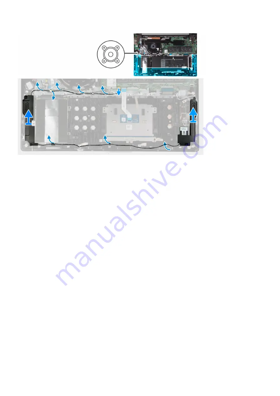
1. Disconnect the speaker cable from the system board.
2. Remove the speaker cable from the routing guides on the palm-rest and antenna assembly.
3. Lift the right speaker from the palm-rest and antenna assembly.
4. Remove the speaker cable from the routing guides on the palm-rest and antenna assembly.
5. Lift the left speaker off the palm-rest and antenna assembly.

Installing the speakers

Prerequisites

If you are replacing a component, remove the existing component before performing the installation procedure.

About this task

The following image indicates the location of the speakers and provides a visual representation of the installation procedure.

30

Removing and installing components

Summary of Contents for Inspiron 7791 2n1

Page 1: ...Inspiron 7791 2n1 Service Manual Regulatory Model P42E Regulatory Type P42E001 ...

Page 2: ...age to hardware or loss of data and tells you how to avoid the problem WARNING A WARNING indicates a potential for property damage personal injury or death 2018 2019 Dell Inc or its subsidiaries All rights reserved Dell EMC and other trademarks are trademarks of Dell Inc or its subsidiaries Other trademarks may be trademarks of their respective owners 2019 08 Rev A00 ...

Page 3: ...y 13 Installing the battery 14 Memory modules 15 Removing the memory modules 15 Installing the memory modules 16 Wireless card 18 Removing the wireless card 18 Installing the wireless card 18 Coin cell battery 19 Removing the coin cell battery 19 Installing the coin cell battery 20 Hard drive 21 Removing the hard drive 21 Installing the hard drive 22 Fan 24 Removing the fan 24 Installing the fan 2...

Page 4: ...he power button with fingerprint reader 52 Palm rest and antenna assembly 53 Removing the palm rest and antenna assembly 53 Installing the palm rest and antenna assembly 54 3 Device drivers 55 Downloading the audio driver 55 Downloading the network driver 55 Downloading the chipset driver 56 Downloading the media card reader driver 56 Downloading the WiFi driver 57 Downloading the USB driver 57 Do...

Page 5: ...de your computer ground yourself by using a wrist grounding strap or by periodically touching an unpainted metal surface such as the metal at the back of the computer While you work periodically touch an unpainted metal surface to dissipate static electricity which could harm internal components CAUTION When you disconnect a cable pull on its connector or on its pull tab not on the cable itself So...

Page 6: ...ield Service kit includes three main components anti static mat wrist strap and bonding wire Components of an ESD field service kit The components of an ESD field service kit are Anti Static Mat The anti static mat is dissipative and parts can be placed on it during service procedures When using an anti static mat your wrist strap should be snug and the bonding wire should be connected to the mat ...

Page 7: ...ice and that they use anti static bags for transporting sensitive components Transporting sensitive components When transporting ESD sensitive components such as replacement parts or parts to be returned to Dell it is critical to place these parts in anti static bags for safe transport Lifting equipment Adhere to the following guidelines when lifting heavy weight equipment CAUTION Do not lift grea...

Page 8: ...e when replacing a component NOTE Screw color may vary with the configuration ordered Table 1 Screw list Component Secured to Screw type Quantity Screw image Base cover Palm rest and antenna assembly M2x4 8 Battery Palm rest and antenna assembly M2x3 2 Wireless card bracket Wireless card and Palm rest and antenna assembly M2x3 1 Right display hinge I O board M2 5x5 3 I O board Palm rest and antenn...

Page 9: ... 2 Keyboard bracket Palm rest and antenna assembly M1 2x1 8 37 Keyboard Palm rest and antenna assembly M1 2x1 5 5 Base cover Removing the base cover Prerequisites 1 Follow the procedure in Before working inside your computer About this task The following image indicates the location of the base cover and provides a visual representation of the removal procedure Removing and installing components 9...

Page 10: ... to the palm rest assembly 3 Using a plastic scribe pry the base cover starting from the hinges and continue to pry the base cover from the slots on the palm rest assembly CAUTION Do not pry the base cover from the middle as it might damage the chassis 4 Carefully remove the base cover off the palm rest assembly 10 Removing and installing components ...

Page 11: ...es If you are replacing a component remove the existing component before performing the installation procedure About this task The following image indicates the location of the base cover and provides a visual representation of the installation procedure Removing and installing components 11 ...

Page 12: ...12 Removing and installing components ...

Page 13: ...tery Do not bend the battery Do not use tools of any kind to pry on or against the battery Ensure any screws during the servicing of this product are not lost or misplaced to prevent accidental puncture or damage to the battery and other system components If a battery gets stuck in a device as a result of swelling do not try to free it as puncturing bending or crushing a Lithium ion battery can be...

Page 14: ... the palm rest assembly 4 Lift the battery off the palm rest assembly Installing the battery Prerequisites If you are replacing a component remove the existing component before performing the installation procedure About this task The following image indicates the location of the battery and provides a visual representation of the installation procedure 14 Removing and installing components ...

Page 15: ...ect the battery cable to the system board Next steps 1 Install the base cover 2 Follow the procedure in After working inside your computer Memory modules Removing the memory modules Prerequisites 1 Follow the procedure in Before working inside your computer 2 Remove the base cover About this task The following image indicates the location of the base cover and provides a visual representation of t...

Page 16: ...ry module slot NOTE Repeat step 2 to step 3 to remove any other memory modules installed in your computer Installing the memory modules Prerequisites If you are replacing a component remove the existing component before performing the installation procedure About this task The following image indicates the location of the base cover and provides a visual representation of the installation procedur...

Page 17: ... into the memory module slot 4 Press the memory module down until it clicks into place NOTE If you do not hear the click remove the memory module and reinstall it NOTE Repeat step 2 to step 4 to install any other memory modules in your computer Next steps 1 Install the base cover 2 Follow the procedure in After working inside your computer Removing and installing components 17 ...

Page 18: ... the wireless card and palm rest assembly 2 Remove the wireless card bracket from the wireless card 3 Disconnect the antenna cables from the wireless card 4 Slide and remove the wireless card from the wireless card slot Installing the wireless card Prerequisites If you are replacing a component remove the existing component before performing the installation procedure About this task The following...

Page 19: ...with the screw hole on the wireless card and palm rest assembly 4 Replace the screw M2x3 that secures the wireless card bracket to the wireless card and palm rest assembly Next steps 1 Install the base cover 2 Follow the procedure in After working inside your computer Coin cell battery Removing the coin cell battery Prerequisites 1 Follow the procedure in Before working inside your computer NOTE R...

Page 20: ... 2 Peel the coin cell battery off the palm rest and antenna assembly Installing the coin cell battery Prerequisites If you are replacing a component remove the existing component before performing the installation procedure About this task The following image indicates the location of the coin cell battery and provides a visual representation of the installation procedure 20 Removing and installin...

Page 21: ...the base cover 3 Follow the procedure in After working inside your computer Hard drive Removing the hard drive Prerequisites 1 Follow the procedure in Before working inside your computer 2 Remove the base cover About this task The following image indicates the location of the hard drive and provides a visual representation of the removal procedure Removing and installing components 21 ...

Page 22: ...om the hard drive assembly 5 Remove the four screws M3x3 that secure the hard drive bracket to the hard drive 6 Lift the hard drive off of the hard drive bracket Installing the hard drive Prerequisites If you are replacing a component remove the existing component before performing the installation procedure About this task The following image indicates the location of the hard drive and provides ...

Page 23: ...the screw holes on the hard drive assembly with the screw holes on the palm rest and antenna assembly 5 Replace the three M2x3 screws that secure the hard drive assembly to the palm rest and antenna assembly 6 Route the hard drive cable through the routing guides on the palm rest and antenna assembly and connect the hard drive cable to the system board Next steps 1 Install the base cover 2 Follow ...

Page 24: ...oval procedure Steps 1 Remove the three screws M2 5x5 that secure the right display hinge to the I O board and palm rest and antenna assembly 2 Lift the right display hinge 3 Disconnect the display cable from the system board 4 Remove the display cable from the routing guides on the palm rest and antenna assembly and peel the tape that secures the display cable to the palm rest and antenna assembl...

Page 25: ...e existing component before performing the installation procedure About this task The following image indicates the location of the fan and provides a visual representation of the installation procedure Steps 1 Using the alignment posts place the fan on the palm rest and antenna assembly 2 Replace the two M2x3 screws that secure the system fan to the palm rest and antenna assembly 3 Connect the fa...

Page 26: ...ver 3 Remove the battery About this task The following image indicates the location of the touchpad and provides a visual representation of the removal procedure Steps 1 Remove the three M2x3 screws that secure the touchpad bracket to the palm rest and antenna assembly 2 Lift the touchpad bracket off the palm rest and antenna assembly 3 Open the latch and disconnect the touchpad cable from the tou...

Page 27: ...pe that secures the touchpad to the palm rest and antenna assembly 4 Slide the touchpad cable into the connector on the touchpad and close the latch to secure the cable 5 Place the touchpad bracket into the slot on the palm rest and antenna assembly 6 Replace the three screws M2x3 that secure the touchpad bracket to the palm rest and antenna assembly Next steps 1 Install the battery 2 Install the ...

Page 28: ...er port to the palm rest and antenna assembly 5 Remove the screw M2x3 that secures the power adapter port to the palm rest and antenna assembly 6 Lift the power adapter port along with its cable off the palm rest and antenna assembly Installing the power adapter port Prerequisites If you are replacing a component remove the existing component before performing the installation procedure About this...

Page 29: ... Close the left display hinge 6 Replace the two screws M2 5x5 that secure the left display hinge to the system board Next steps 1 Install the battery 2 Install the base cover 3 Follow the procedure in After working inside your computer Speakers Removing the speakers Prerequisites 1 Follow the procedure in Before working inside your computer 2 Remove the base cover About this task The following ima...

Page 30: ... the routing guides on the palm rest and antenna assembly 5 Lift the left speaker off the palm rest and antenna assembly Installing the speakers Prerequisites If you are replacing a component remove the existing component before performing the installation procedure About this task The following image indicates the location of the speakers and provides a visual representation of the installation p...

Page 31: ...ent posts and rubber grommets place the right speaker on the slots of the palm rest and antenna assembly 4 Connect the speaker cable to the system board Next steps 1 Install the base cover 2 Follow the procedure in After working inside your computer Heat sink Removing the heatsink Prerequisites 1 Follow the procedure in Before working inside your computer 2 Remove the base cover 3 Remove the batte...

Page 32: ...ink off the system board Installing the heatsink Prerequisites If you are replacing a component remove the existing component before performing the installation procedure About this task The following image indicates the location of the base cover and provides a visual representation of the installation procedure 32 Removing and installing components ...

Page 33: ...he battery 2 Install the base cover 3 Follow the procedure in After working inside your computer Display assembly Removing the display assembly Prerequisites 1 Follow the procedure in Before working inside your computer 2 Remove the base cover 3 Remove the battery About this task The following image indicates the location of display assembly and provides a visual representation of the removal proc...

Page 34: ...34 Removing and installing components ...

Page 35: ...Removing and installing components 35 ...

Page 36: ...to the palm rest and antenna assembly 5 Remove the two screws M2 5x3 5 that secure the left display hinge to the I O board and palm rest and antenna assembly 6 Using the pull tab disconnect the display cable from the system board 7 Remove the display cable through the display hinge cover 8 Lift the display assembly off the palm rest and antenna assembly Installing the display assembly Prerequisite...

Page 37: ...About this task The following image indicates the location of display assembly and provides a visual representation of the installation procedure Removing and installing components 37 ...

Page 38: ...eplace the three screws M2x1 9 that secure the right hinge to the palm rest and antenna assembly 5 Replace the two screws M2 5x3 5 that secure the left display hinge to the I O board and palm rest and antenna assembly 6 Route the display cable through the display hinge cover 7 Connect the display cable on to the connector on the system board Next steps 1 Install the battery 2 Install the base cove...

Page 39: ...s 1 Remove the three screws M2 5x5 that secure the right display hinge to the I O board 2 Open the right display hinge at an angle of 90 degree 3 Using the pull tab disconnect the I O board cable from the I O board 4 Open the latch and disconnect the fingerprint reader cable from the I O board 5 Disconnect the coin cell battery cable from the I O board 6 Remove the screw M2x4 that secure the I O b...

Page 40: ...Slide the fingerprint reader cable into the connector on the I O board and close the latch to secure the cable 6 Connect the I O board cable to the I O board 7 Close the right display hinge 8 Replace the three screws M2 5x5 that secure the right display hinge to the I O board Next steps 1 Install the battery 2 Install the base cover 3 Follow the procedure in After working inside your computer Syst...

Page 41: ... Power adapter port cable 3 Keyboard backlit cable 4 Keyboard cable 5 Touchpad cable 6 Speaker cable 7 Hard drive cable 8 I O board cable 9 Touchscreen cable 10 Fan cable The following image indicates the location of the system board and provides a visual representation of the removal procedure Removing and installing components 41 ...

Page 42: ...and disconnect the keyboard cable from the system board 10 Open the latch and disconnect the keyboard backlit cable from the system board 11 Peel the tape that secures the power adapter port to the system board 12 Disconnect the power adapter cable from the system board 13 Using the pull tab disconnect the display cable from the system board 14 Remove the two screws M2x2 that secure the system boa...

Page 43: ...t cable 4 Keyboard cable 5 Touchpad cable 6 Speaker cable 7 Hard drive cable 8 I O board cable 9 Touchscreen cable 10 Fan cable The following image indicates the location of the system board and provides a visual representation of the installation procedure Removing and installing components 43 ...

Page 44: ...44 Removing and installing components ...

Page 45: ...he system board and close the latch to secure the cable 13 Connect the fan cable on to the connector on the system board 14 Close the display hinge 15 Replace the two screws M2 5x5 that secures the right display hinge to the system board Next steps 1 Install the heat sink 2 Install the wireless card 3 Install the memory modules 4 Install the battery 5 Install the base cover 6 Follow the procedure ...

Page 46: ... secure the keyboard bracket to the palm rest and antenna assembly 3 Remove the fingerprint reader cable through the slot on the keyboard bracket and lift the keyboard bracket off the palm rest and antenna assembly 4 Lift the keyboard bracket off the palm rest and antenna assembly 46 Removing and installing components ...

Page 47: ...component remove the existing component before performing the installation procedure About this task The following image indicates the location of the keyboard bracket and provides a visual representation of the installing procedure Removing and installing components 47 ...

Page 48: ...e power adapter port 3 Install the display assembly 4 Install the speakers 5 Install the touchpad 6 Install the heat sink 7 Install the fan 8 Install the I O board 9 Install the wireless card 10 Remove the hard drive 11 Install the memory modules 12 Install the battery 13 Install the base cover 14 Follow the procedure in After working inside your computer Keyboard Removing the keyboard Prerequisit...

Page 49: ...rd and provides a visual representation of the removal procedure Steps 1 Remove the five M1 2x1 5 screws that secure the keyboard to the palm rest and antenna assembly 2 Remove the keyboard from the palm rest and antenna assembly Installing the keyboard Prerequisites If you are replacing a component remove the existing component before performing the installation procedure About this task The foll...

Page 50: ...ystem board 3 Install the keyboard bracket 4 Install the power adapter port 5 Install the display assembly 6 Install the speakers 7 Install the touchpad 8 Install the heat sink 9 Install the fan 10 Install the I O board 11 Install the wireless card 12 Remove the hard drive 13 Install the memory modules 14 Install the battery 15 Install the base cover 16 Follow the procedure in After working inside...

Page 51: ...ow the procedure from step 1 to step 2 in Removing the keyboard bracket About this task The following image indicates the location of the power button with fingerprint reader and provides a visual representation of the removal procedure Steps 1 Slide and remove the power button with fingerprint reader cable from the keyboard bracket 2 Remove the fingerprint reader cable through the routing guides ...

Page 52: ...e keyboard bracket 3 Route the fingerprint reader cable through the routing guides on the keyboard bracket 4 Slide and insert the power button with fingerprint reader cable on the slot on the keyboard bracket Next steps 1 Follow procedure from step 3 to step 4 inInstalling the keyboard bracket 2 Install the system board 3 Install the I O board 4 Install the display assembly 5 Install the fan 6 Ins...

Page 53: ... speakers 9 Remove the fan 10 Remove the display assembly 11 Remove the I O board 12 Remove the system board 13 Remove the keyboard bracket 14 Install the power button with fingerprint reader 15 Remove the keyboard About this task The following image indicates the location of the palm rest and antenna assembly and provides a visual representation of the removal procedure Steps After performing the...

Page 54: ...st and antenna assembly on a clean and flat surface Next steps 1 Install the keyboard 2 Install the power button with fingerprint reader 3 Install the keyboard bracket 4 Install the system board 5 Install the I O board 6 Install the display assembly 7 Install the fan 8 Install the speakers 9 Install the wireless card 10 Install the coin cell battery 11 Install the hard drive 12 Install the memory ...

Page 55: ...on summary to identify if manual installation is necessary 13 For manual download and installation click Category 14 Click Audio in the drop down list 15 Click Download to download the audio driver for your computer 16 After the download is complete navigate to the folder where you saved the audio driver file 17 Double click the audio driver file icon and follow the instructions on the screen to i...

Page 56: ...ick View Drivers for My System 9 Click Download and Install to download and install all driver updates detected for your computer 10 Select a location to save the files 11 If prompted approve requests from User Account Control to make changes on the system 12 The application installs all drivers and updates identified NOTE Not all files can be installed automatically Review the installation summar...

Page 57: ... Review and agree to the Terms and Conditions to use SupportAssist then click Continue 7 If necessary your computer starts to download and install SupportAssist NOTE Review on screen instructions for browser specific instructions 8 Click View Drivers for My System 9 Click Download and Install to download and install all driver updates detected for your computer 10 Select a location to save the fil...

Page 58: ...l com support 3 Enter the Service Tag of your computer and then click Submit NOTE If you do not have the Service Tag use the auto detect feature or manually browse for your computer model 4 Click Drivers downloads 5 Click the Detect Drivers button 6 Review and agree to the Terms and Conditions to use SupportAssist then click Continue 7 If necessary your computer starts to download and install Supp...

Page 59: ...agnostic 3 0 Running the ePSA diagnostics Steps 1 Turn on your computer 2 As the computer boots press the F12 key as the Dell logo appears 3 On the boot menu screen select the Diagnostics option 4 Click the arrow at the bottom left corner Diagnostics front page is displayed 5 Click the arrow in the lower right corner to go to the page listing The items detected are listed 6 To run a diagnostic tes...

Page 60: ...ff Camera is not in use Caps Lock status light Indicates whether Caps Lock is enabled or disabled Solid white Caps Lock enabled Off Caps Lock disabled Recovering the operating system When your computer is unable to boot to the operating system even after repeated attempts it automatically starts Dell SupportAssist OS Recovery Dell SupportAssist OS Recovery is a standalone tool that is preinstalled...

Page 61: ...ng system installed on your computer 6 Scroll down the page and expand BIOS 7 Click Download to download the latest version of the BIOS for your computer 8 After the download is complete navigate to the folder where you saved the BIOS update file 9 Double click the BIOS update file icon and follow the instructions on the screen WiFi power cycle About this task If your computer is unable to access ...

Page 62: ...r computer 2 Disconnect the power adapter from your computer 3 Press and hold the power button for 15 seconds to drain the flea power 4 Connect the power adapter to your computer 5 Turn on your computer 62 Troubleshooting ...

Page 63: ... the related articles Learn and know the following information about your product Product specifications Operating system Setting up and using your product Data backup Troubleshooting and diagnostics Factory and system restore BIOS information See Me and My Dell at www dell com support manuals To locate the Me and My Dell relevant to your product identify your product through one of the following ...

Reviews: