


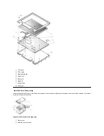


1.
Remove the two 5-mm screws securing the heat exchanger.
2.
Disconnect the fan cable from the connector labeled JP17 on the system board.
3.
Remove the heat exchanger/fan.
4.
Inspect the two thermal pads on the bottom of the heat exchanger and replace them if necessary.
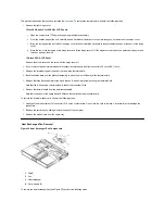
To remove the heat exchanger/fan without removing the palmrest assembly, perform the following steps:
1.
Remove the two 5-mm screws securing the heat exchanger.
2.
Disconnect the fan cable from connector JP17 on the system board.
3.
Lift the heat exchanger and rotate it upward.
4.
Slide the heat exchanger/fan toward the front of the computer until the fan is completely clear of the overhanging palmrest plastic.
5.
Lift the heat exchanger/fan out at an angle.
6.
Inspect the two thermal pads on the bottom of the heat exchanger and replace them if necessary.
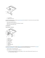
When reinstalling the heat exchanger/fan, be sure to reconnect the fan cable to connector JP17 on the system board; if you have an internal
modem, there is an identical connector (JP2) next to JP17. The modem connector is color-coded red.
Processor Board Removal
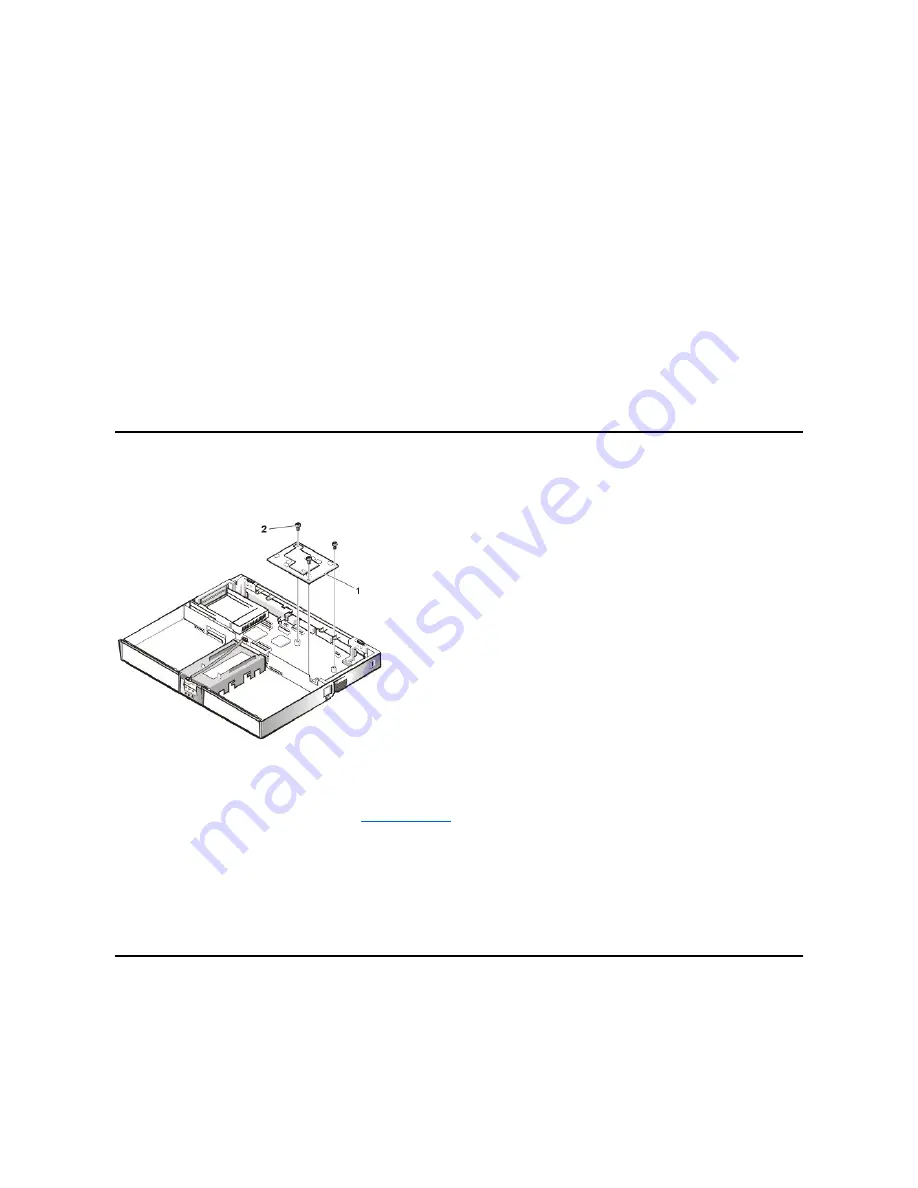
Figure 21. Processor Board Components
This procedure assumes that you have removed the
. To remove the processor board (see Figure 21), perform the following
steps:
1.
Remove the three 5-mm screws securing the processor board to the system board.
2.
Gently pull the processor board off of connector JP15 on the system board. Do not rock the board to remove it, because this may damage
the connectors.
When reinstalling the processor board, align the board with the notch on the system board connector. Press down on the left side of the board over
the system board connector. This is the best spot to apply pressure to seat the processor correctly on connector JP15.
15-Inch LCD Removal
Figure 22. 15-Inch LCD Components
1
Processor board
2
5-mm screws (3)
Summary of Contents for Inspiron 7500
Page 6: ...Back to Contents Page AC Adapter Dell Inspiron 7500 ...
Page 7: ...Back to Contents Page Audio Jacks Dell Inspiron 7500 ...
Page 10: ...Back to Contents Page Component Locations Back View Dell Inspiron 7500 ...
Page 12: ...Back to Contents Page Battery Charge Gauge Dell Inspiron 7500 ...
Page 13: ...Back to Contents Page Removing and Installing a Battery Dell Inspiron 7500 ...
Page 26: ...Back to Contents Page ...
Page 38: ...Exploded View of 13 3 Inch Display Assembly Dell Inspiron 7500 ...
Page 39: ...Exploded View of 14 1 Inch Display Assembly Dell Inspiron 7500 ...
Page 44: ...Back to Contents Page Exploded View of Computer Dell Inspiron 7500 ...
Page 47: ...Back to Contents Page Component Locations Front View Dell Inspiron 7500 New artwork pending ...
Page 54: ...Back to Contents Page I O Connectors Dell Inspiron 7500 ...
Page 60: ...Back to Contents Page 30 Cone of Infrared Light Dell Inspiron 7500 ...
Page 64: ...Back to Contents Page Embedded Numeric Keypad Dell Inspiron 7500 ...
Page 89: ...Back to Contents Page PC Card Slots Dell Inspiron 7500 ...
Page 103: ...Back to Contents Page Removing the Memory Module Dell Inspiron 7500 ...
Page 104: ...Back to Contents Page Removing the Memory Module Cover Dell Inspiron 7500 ...
Page 136: ...Back to Contents Page Removing the Hard Disk Drive Dell Inspiron 7500 ...
Page 138: ...Back to Contents Page Removing Devices From the Media Bay Dell Inspiron 7500 ...
Page 140: ...Back to Contents Page Security Cable Slot Dell Inspiron 7500 ...
Page 159: ...Back to Contents Page Touch Pad Dell Inspiron 7500 ...


