background image

Steps

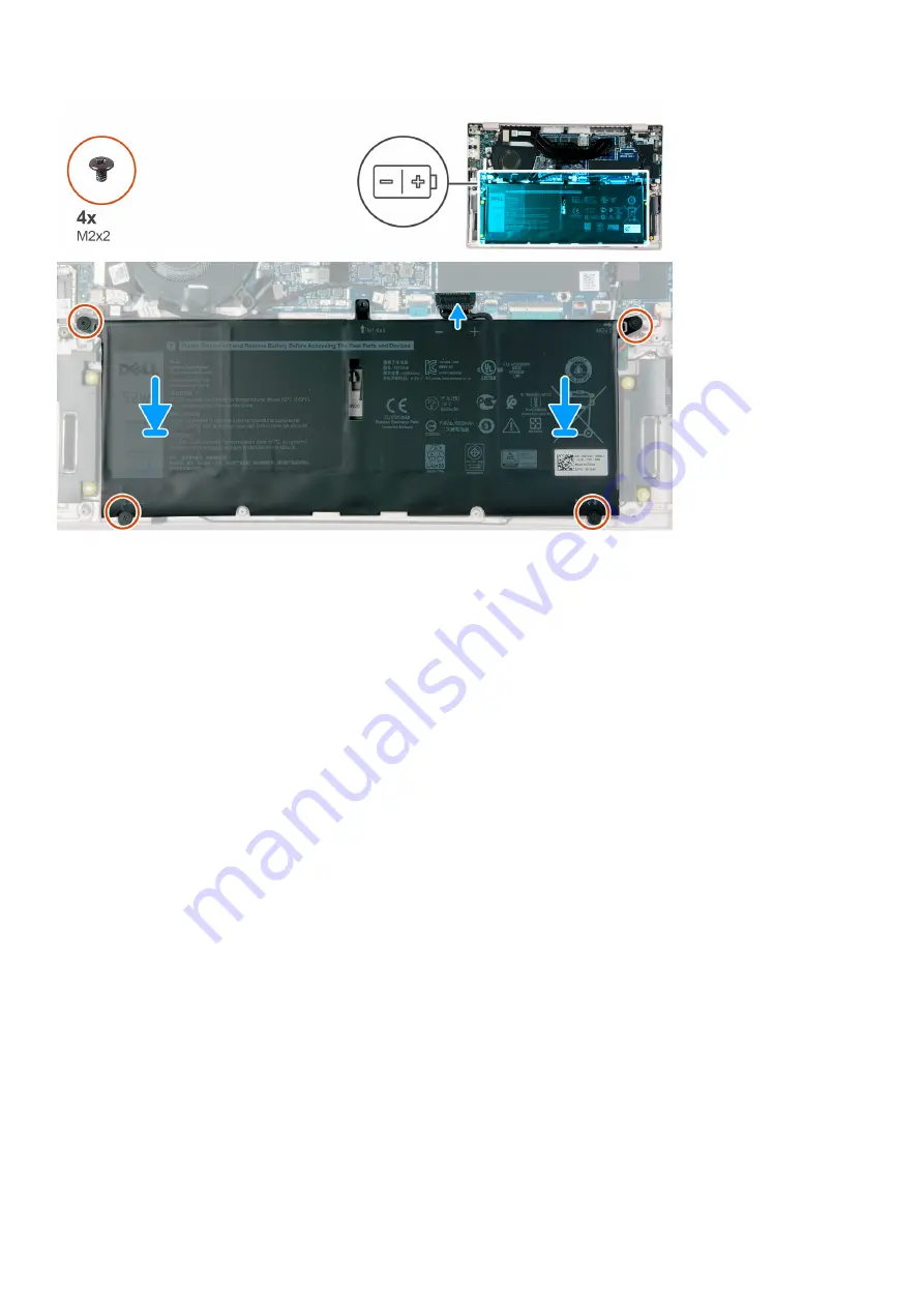
1. Using the alignment post, place the battery on the palm-rest assembly.
2. Connect the battery cable to the system board.
3. Replace the four screws (M2x2) that secure the battery to the palm-rest assembly.

Next steps

1. Install the 

base cover

.

2. Follow the procedure in 

after working inside your computer

.

Coin-cell battery

Removing the coin-cell battery

Prerequisites

1. Follow the procedure in 

before working inside your computer

.

2. Remove the 

base cover

.

3. Remove the 

battery

.

About this task

The following image indicates the location of the coin-cell battery and provides a visual representation of the removal procedure.

22

Removing and installing components

Summary of Contents for Inspiron 7490 P115G

Page 1: ...Inspiron 7490 Service Manual Regulatory Model P115G Regulatory Type P115G001 ...

Page 2: ...age to hardware or loss of data and tells you how to avoid the problem WARNING A WARNING indicates a potential for property damage personal injury or death 2018 2019 Dell Inc or its subsidiaries All rights reserved Dell EMC and other trademarks are trademarks of Dell Inc or its subsidiaries Other trademarks may be trademarks of their respective owners 2019 07 Rev A00 ...

Page 3: ... M 2 2230 solid state drive 19 Battery 20 Lithium ion battery precautions 20 Removing the battery 20 Installing the battery 21 Coin cell battery 22 Removing the coin cell battery 22 Installing the coin cell battery 23 WWAN card 24 Removing the WWAN card 24 Installing the WWAN card 25 Heat sink 27 Removing the heatsink on computers shipped with discrete graphics card 27 Installing the heat sink on ...

Page 4: ...7 Installing the system board 52 Keyboard 56 Removing the keyboard 56 Installing the keyboard 57 Palmrest 59 Removing the palmrest 59 Installing the palmrest 60 3 Device drivers 61 Downloading the audio driver 61 Downloading the network driver 61 Downloading the chipset driver 62 Downloading the media card reader driver 62 Downloading the WiFi driver 63 Downloading the USB driver 63 Downloading th...

Page 5: ...m diagnostic lights 76 Diagnostics 77 M BIST 78 LCD Built in Self Test BIST 78 Recovering the operating system 78 Flashing BIOS USB key 78 Flashing the BIOS 79 WiFi power cycle 79 Flea power release 79 Enabling Intel Optane memory 80 Disabling Intel Optane memory 80 6 Getting help and contacting Dell 81 Contents 5 ...

Page 6: ...de your computer ground yourself by using a wrist grounding strap or by periodically touching an unpainted metal surface such as the metal at the back of the computer While you work periodically touch an unpainted metal surface to dissipate static electricity which could harm internal components CAUTION When you disconnect a cable pull on its connector or on its pull tab not on the cable itself So...

Page 7: ...ield Service kit includes three main components anti static mat wrist strap and bonding wire Components of an ESD field service kit The components of an ESD field service kit are Anti Static Mat The anti static mat is dissipative and parts can be placed on it during service procedures When using an anti static mat your wrist strap should be snug and the bonding wire should be connected to the mat ...

Page 8: ...ice and that they use anti static bags for transporting sensitive components Transporting sensitive components When transporting ESD sensitive components such as replacement parts or parts to be returned to Dell it is critical to place these parts in anti static bags for safe transport Lifting equipment Adhere to the following guidelines when lifting heavy weight equipment CAUTION Do not lift grea...

Page 9: ...mponent is replaced NOTE Some computers have magnetic surfaces Ensure that the screws are not left attached to such surface when replacing a component NOTE Screw color may vary with the configuration ordered Table 1 Screw list Component Secured to Screw type Quantity Screw image Base cover Palm rest assembly M2x3 5 6 Battery Palm rest assembly M2x2 4 Solid state drive shield NOTE Available only on...

Page 10: ...lm rest assembly M1 4x2 3 2 System board Palm rest assembly M2x3 1 Keyboard Palm rest assembly M1 2x1 5 28 Fan bracket Keyboard M1 4x2 3 1 Nano SIM card tray Removing the Nano SIM card tray Prerequisites 1 Follow the procedure in before working inside your computer About this task The following image indicates the location of the Nano SIM card tray and provides a visual representation of the remov...

Page 11: ...f you are replacing a component remove the existing component before performing the installation procedure About this task The following image indicates the location of the Nano SIM card tray and provides a visual representation of the removal procedure NOTE The Nano SIM card slot is available in your computer depending on the region and configuration you ordered Removing and installing components...

Page 12: ...ing the base cover Prerequisites 1 Follow the procedure in before working inside your computer About this task The following image indicates the location of the base cover and provides a visual representation of the removal procedure 12 Removing and installing components ...

Page 13: ...eft corner of the palm rest assembly 4 Lift the base cover off the palm rest assembly Installing the base cover Prerequisites If you are replacing a component remove the existing component before performing the installation procedure About this task The following image indicates the location of the base cover and provides a visual representation of the removal procedure Removing and installing com...

Page 14: ...embly and snap the base cover into place 2 Replace the six screws M2x3 5 that secure the base cover to the palm rest assembly 3 Tighten the three captive screws that secure the base cover to the palm rest assembly 14 Removing and installing components ...

Page 15: ...0 solid state drive Intel Optane is supported in computers shipped with WLAN card only About this task You need to disable the Intel Optane device before removing it from your computer For more information about disabling the Intel Optane device see Disabling Intel Optane memory The following image indicates the location of the M 2 2280 solid state drive Intel Optane and provides a visual represen...

Page 16: ...lid state drive slot on the system board Installing the M 2 2280 solid state drive Intel Optane Prerequisites If you are replacing a component remove the existing component before performing the installation procedure NOTE M 2 2280 solid state drive Intel Optane is supported in computers shipped with WLAN card only About this task Enable the Intel Optane device after you replace it For more inform...

Page 17: ...he solid state drive slot on the system board NOTE Solid state drive shield is available only in computers that are shipped with Intel Optane or solid state drive that has a capacity of more than 512 GB 4 Replace the screw M2x3 that secures the solid state drive shield to the system board 5 Connect the battery cable to the system board Next steps 1 Install the base cover 2 Follow the procedure in ...

Page 18: ...state drive and provides a visual representation of the removal procedure NOTE Computers shipped with WWAN card supports only M 2 2230 solid state drive Steps 1 Disconnect the battery cable from the system board 2 Remove the screw M2x3 that secures the solid state drive bracket to the system board 3 Slide and remove the solid state drive bracket off the M 2 2230 solid state drive on the system boa...

Page 19: ... remove the existing component before performing the installation procedure About this task The following image indicates the location of the M 2 2230 solid state drive and provides a visual representation of the installation procedure NOTE Computers shipped with WWAN card supports only M 2 2230 solid state drive Steps 1 Align the notch on the M 2 2230 solid state drive with the tab on the solid s...

Page 20: ...he battery Do not bend the battery Do not use tools of any kind to pry on or against the battery Ensure any screws during the servicing of this product are not lost or misplaced to prevent accidental puncture or damage to the battery and other system components If a battery gets stuck in a device as a result of swelling do not try to free it as puncturing bending or crushing a Lithium ion battery ...

Page 21: ...tery off the palm rest assembly Installing the battery Prerequisites If you are replacing a component remove the existing component before performing the installation procedure About this task The following image indicates the location of the battery and provides a visual representation of the installation procedure Removing and installing components 21 ...

Page 22: ...the base cover 2 Follow the procedure in after working inside your computer Coin cell battery Removing the coin cell battery Prerequisites 1 Follow the procedure in before working inside your computer 2 Remove the base cover 3 Remove the battery About this task The following image indicates the location of the coin cell battery and provides a visual representation of the removal procedure 22 Remov...

Page 23: ...ssembly Installing the coin cell battery Prerequisites If you are replacing a component remove the existing component before performing the installation procedure About this task The following image indicates the location of the coin cell battery and provides a visual representation of the installation procedure Removing and installing components 23 ...

Page 24: ...inside your computer WWAN card Removing the WWAN card Prerequisites NOTE This procedure is only applicable for computers shipped with a WWAN configuration 1 Follow the procedure in Before working inside your computer 2 Remove the base cover 3 Remove the battery About this task The following image indicates the location of WWAN card and provides a visual representation of the removal procedure 24 R...

Page 25: ...Slide and remove the WWAN card from the WWAN card slot Installing the WWAN card Prerequisites NOTE This procedure is only applicable for computers shipped with a WWAN configuration If you are replacing a component remove the existing component before performing the installation procedure About this task The following image indicates the location of WWAN card and provides a visual representation of...

Page 26: ...lowing table provides the antenna cable color scheme for the WWAN card supported by your computer Table 2 Antenna cable color scheme Connectors on the WWAN card Antenna cable color M White Grey M1 Blue M2 Orange D G Black Grey 3 Replace the screw M2x3 that secures the WWAN bracket to the WWAN card 4 Place the WWAN card shield on the WWAN card Next steps 1 Install the battery 2 Install the base cov...

Page 27: ...es a visual representation of the installation procedure Steps 1 Peel the tapes that secure the fan to the fan to the heat sink 2 In the reverse sequential order 5 4 3 2 1 as indicated on the heat sink remove the five screws M2x3 that secure the heat sink to the system board 3 Lift the heat sink off the system board Installing the heat sink on computers shipped with discrete graphics card Prerequi...

Page 28: ...les to the shield on the heat sink 5 Adhere the tapes that secure the I O board cable to the shield on the heat sink 6 Adhere the tapes that secure the fan to the heat sink Next steps 1 Install the battery 2 Install the base cover 3 Follow the procedure in After working inside your computer Removing the heatsink on computers shipped with integrated graphics card Prerequisites 1 Follow the procedur...

Page 29: ...shield off the heat sink 5 In the reverse sequential order 4 3 2 1 as indicated on the heat sink remove the four screws M2x3 that secure the heat sink to the system board 6 Lift the heat sink off the system board Installing the heat sink on computers shipped with integrated graphics card Prerequisites If you are replacing a component remove the existing component before performing the installation...

Page 30: ...t sink with the screw holes on the system board 2 In sequential order 1 2 3 4 as indicated on the heat sink replace the four screws M2x3 that secure the heat sink to the system board 3 Adhere the tapes that secure the fan to the heat sink Next steps 1 Install the battery 2 Install the base cover 3 Follow the procedure in After working inside your computer 30 Removing and installing components ...

Page 31: ...tion of fan and provides a visual representation of the removal procedure Steps 1 Disconnect the fan cable from the I O board 2 Peel the tapes 3 that secure the I O board cable to the fan 3 Peel the tapes 2 that secure the fan to the heat sink and the palm rest assembly 4 Remove the three screws M2x3 that secure the fan to the palm rest assembly 5 Slide and lift the fan slightly off the palm rest ...

Page 32: ...Steps 1 Place and align the screw holes on the fan with the screw holes on the palm rest assembly 2 Replace the three screws M2x3 that secure the fan to the palm rest assembly 3 Adhere the tapes 2 that secure the fan to the heat sink and the palm rest assembly 4 Adhere the tapes 3 that secure the I O board cable to the fan 5 Connect the fan cable to the system board Next steps 1 Install the batter...

Page 33: ...rocedure Steps 1 Disconnect the fan cable from the I O board 2 Peel the tape that secures the fan to the heat sink and the palm rest assembly 3 Remove the three screws M2x3 that secure the fan to the palm rest assembly 4 Slide and lift the fan slightly off the palm rest assembly Installing the fan on computers shipped with integrated graphics card Prerequisites If you are replacing a component rem...

Page 34: ...mbly 3 Adhere the tapes 2 that secure the fan to the heat sink and the palm rest assembly 4 Adhere the tapes 3 that secure the I O board cable to the fan 5 Connect the fan cable to the system board Next steps 1 Install the battery 2 Install the base cover 3 Follow the procedure in after working inside your computer Speakers Removing the speaker Prerequisites 1 Follow the procedure in before workin...

Page 35: ...ker cable from the routing guides on the palm rest assembly NOTE Note the position of the rubber grommets before lifting the speakers 4 Lift the speakers along with the cable off the palm rest assembly Installing the speaker Prerequisites If you are replacing a component remove the existing component before performing the installation procedure About this task The following image indicates the loc...

Page 36: ...e palm rest assembly 4 Connect the speaker cable to the I O board Next steps 1 Install the battery 2 Install the base cover 3 Follow the procedure in after working inside your computer Touchpad Removing the touchpad Prerequisites 1 Follow the procedure in before working inside your computer 2 Remove the base cover 3 Remove the battery About this task The following image indicates the location of t...

Page 37: ...hpad 4 Slide and lift the touchpad along with the bracket off the palm rest assembly Installing the touchpad Prerequisites If you are replacing a component remove the existing component before performing the installation procedure About this task The following image indicates the location of touchpad and provides a visual representation of the installation procedure Removing and installing compone...

Page 38: ...e touchpad and close the latch to secure the cable Next steps 1 Install the battery 2 Install the base cover 3 Follow the procedure in after working inside your computer Display assembly Removing the display assembly Prerequisites 1 Follow the procedure in before working inside your computer 2 Remove the base cover 3 Remove the battery About this task The following image indicates the location of ...

Page 39: ...Steps 1 Remove the three screws M2x3 5 that secures the display cable bracket to the system board 2 Lift the display cable bracket off the system board Removing and installing components 39 ...

Page 40: ...ition that allows access to the screws on the display hinges 7 Remove the four screws M2x4 5 that secure the display hinges to the palm rest assembly 8 Carefully lift the display assembly from the palm rest assembly 9 Carefully place the display assembly on a clean and flat surface Installing the display assembly Prerequisites If you are replacing a component remove the existing component before p...

Page 41: ...alm rest assembly at the edge of the table 2 Align the screw holes on the palm rest assembly with the screw holes on the display hinges 3 Close the display and turn the computer over Removing and installing components 41 ...

Page 42: ... display cable 8 Replace the three screws M2x3 5 that secure the display cable bracket to the system board Next steps 1 Install the battery 2 Install the base cover 3 Follow the procedure in after working inside your computer I O board Removing the I O board Prerequisites 1 Follow the procedure in before working inside your computer 2 Remove the base cover 3 Remove the battery 4 Remove the fan dis...

Page 43: ...alm rest assembly Installing the I O board Prerequisites If you are replacing a component remove the existing component before performing the installation procedure About this task The following image indicates the location of I O board and provides a visual representation of the installation procedure Steps 1 Using the alignment post place the I O board on the palm rest assembly 2 Replace the thr...

Page 44: ...ing inside your computer 2 Remove the base cover 3 Remove the battery 4 Remove the fan discrete graphics card or fan integrated graphics card whichever applicable 5 Remove the I O board About this task The following image indicates the location of power button and provides a visual representation of the removal procedure Steps 1 Remove the two screws M1 4x2 3 that secure the power button to the pa...

Page 45: ... assembly 2 Replace the two screws M1 4x2 3 that secure the power button to the palm rest assembly Next steps 1 Install the I O board 2 Install the fan discrete graphics card or fan integrated graphics card whichever applicable 3 Install the battery 4 Install the base cover 5 Follow the procedure in After working inside your computer Power button with optional fingerprint reader Removing the power...

Page 46: ...on cable from the fingerprint reader board 3 Peel the tapes that secure the finger print reader cable and the fingerprint reader board to the keyboard 4 Lift the power button with optional fingerprint reader along with the finger print reader cable off the palm rest assembly Installing the power button with optional fingerprint reader Prerequisites NOTE This procedure is only applicable for comput...

Page 47: ...3 Install the battery 4 Install the base cover 5 Follow the procedure in After working inside your computer System board Removing the system board Prerequisites 1 Follow the procedure in before working inside your computer 2 Remove the Nano SIM card tray NOTE The Nano SIM card slot is available in your computer depending on the region and configuration you ordered 3 Remove the base cover 4 Remove ...

Page 48: ...ble available only in touchscreen computers 3 Coin cell battery cable 4 Keyboard backlit cable 5 Keyboard cable 6 Fingerprint reader cable 7 Battery cable 8 Touchpad cable 9 I O board cable The following image indicates the location of system board and provides a visual representation of the removal procedure 48 Removing and installing components ...

Page 49: ...Removing and installing components 49 ...

Page 50: ...50 Removing and installing components ...

Page 51: ...with WWAN card 12 Disconnect the coin cell battery cable from the system board 13 Peel the tape that secures the I O board cable to the system board 14 Open the latch and disconnect the I O board cable from the system board 15 Open the latch and disconnect the fingerprint reader cable from the system board 16 Open the latch and disconnect the touchpad cable from the system board 17 Open the latch ...

Page 52: ...m board Figure 2 System board connectors 1 Display cable 2 Touchscreen cable available only in touchscreen computers 3 Coin cell battery cable 4 Keyboard backlit cable 5 Keyboard cable 6 Fingerprint reader cable 7 Battery cable 8 Touchpad cable 9 I O board cable The following image indicates the location of system board and provides a visual representation of the installation procedure 52 Removing...

Page 53: ...Removing and installing components 53 ...

Page 54: ...54 Removing and installing components ...

Page 55: ... board with the screw holes on the keyboard assembly 3 Connect the keyboard backlit cable to the system board and close the latch to secure the cable 4 Connect the keyboard cable to the system board and close the latch to secure the cable 5 Connect the touchpad cable to the system board and close the latch to secure the cable 6 Connect the fingerprint reader cable to the system board and close the...

Page 56: ...rd or fan integrated graphics card whichever applicable 3 Install the M 2 2280 solid state drive Intel Optane or M 2 2230 solid state drive whichever applicable 4 Install the battery 5 Install the base cover 6 Install the Nano SIM card tray NOTE The Nano SIM card slot is available in your computer depending on the region and configuration you ordered 7 Follow the procedure in after working inside ...

Page 57: ...WWAN card 4 Remove the 28 screws M1 2x1 5 that secure the keyboard to the palmrest 5 Lift the keyboard off the palmrest Installing the keyboard Prerequisites If you are replacing a component remove the existing component before performing the installation procedure About this task The following image indicates the keyboard and provides a visual representation of the installation procedure Removing...

Page 58: ...t secures the fan bracket to the palmrest Next steps 1 Install the system board NOTE The system board can be removed with the heatsink attached to avoid breaking the thermal bond between system board and heatsink 2 Install the power button with optional fingerprint reader 3 Install the I O board 4 Install the speakers 5 Install the heat sink discrete graphics card or heat sink integrated graphics ...

Page 59: ... the fan discrete graphics card or fan integrated graphics card whichever applicable 7 Remove the speakers 8 Remove the heat sink discrete graphics card or heat sink integrated graphics card whichever applicable NOTE The system board can be removed and installed together with the heat sink attached This will simplify the system board removal and avoid breaking the thermal bond between the system b...

Page 60: ...keyboard 2 Install the system board 3 Install the power button with optional fingerprint reader 4 Install the I O board 5 Install the heat sink discrete graphics card or heat sink integrated graphics card whichever applicable 6 Install the speakers 7 Install the fan discrete graphics card or fan integrated graphics card whichever applicable 8 Install the display assembly 9 Install the M 2 2280 sol...

Page 61: ...on summary to identify if manual installation is necessary 13 For manual download and installation click Category 14 Click Audio in the drop down list 15 Click Download to download the audio driver for your computer 16 After the download is complete navigate to the folder where you saved the audio driver file 17 Double click the audio driver file icon and follow the instructions on the screen to i...

Page 62: ...ick View Drivers for My System 9 Click Download and Install to download and install all driver updates detected for your computer 10 Select a location to save the files 11 If prompted approve requests from User Account Control to make changes on the system 12 The application installs all drivers and updates identified NOTE Not all files can be installed automatically Review the installation summar...

Page 63: ... Review and agree to the Terms and Conditions to use SupportAssist then click Continue 7 If necessary your computer starts to download and install SupportAssist NOTE Review on screen instructions for browser specific instructions 8 Click View Drivers for My System 9 Click Download and Install to download and install all driver updates detected for your computer 10 Select a location to save the fil...

Page 64: ...l com support 3 Enter the Service Tag of your computer and then click Submit NOTE If you do not have the Service Tag use the auto detect feature or manually browse for your computer model 4 Click Drivers downloads 5 Click the Detect Drivers button 6 Review and agree to the Terms and Conditions to use SupportAssist then click Continue 7 If necessary your computer starts to download and install Supp...

Page 65: ...ow between the computer s operating system and attached devices such as hard disk video adapter keyboard mouse and printer Entering BIOS setup program About this task Turn on or restart your computer and press F2 immediately Boot Sequence Boot Sequence allows you to bypass the System Setup defined boot device order and boot directly to a specific device for example optical drive or hard drive Duri...

Page 66: ...ry state Health Displays the battery health AC Adapter Displays whether an AC adapter is installed Processor Information Processor Type Displays the processor type Maximum Clock Speed Displays the maximum processor clock speed Core Count Displays the number of cores on the processor Processor L2 Cache Displays the processor L2 Cache size Processor ID Displays the processor identification code Proc...

Page 67: ...le Boot Devices Enables or disables boot devices for this computer Boot Sequence Displays the boot sequence BIOS Setup Advanced Mode Enables or disables advanced BIOS settings Default ON UEFI Boot Path Security Enables or disables the system to prompt the user to enter the Admin password when booting a UEFI boot path from the F12 boot menu Default Always Except Internal HDD Table 5 System setup op...

Page 68: ...les the camera Default ON Keyboard Illumination Configures the operating mode of the keyboard illumination feature Default Disabled The keyboard illumination will always be off Keyboard Backlight Timeout on AC Configures the timeout value for the keyboard when an AC adapter is connected to the computer The keyboard backlight timeout value is only effect when the backlight is enabled Default 10 sec...

Page 69: ...fault ON PPI Bypass for Clear Commands Enables or disables the operating system to skip BIOS Physical Presence Interface PPI user prompts when issuing the Clear command Default OFF Clear Enables or disables the computer to clear the PTT owner information and returns the PTT to the default state Default OFF Intel SGX Enables or disables the Intel Software Guard Extensions SGX to provide a secured e...

Page 70: ...ance Intel Hyper Threading Technology Enables or disables the Intel Hyper Threading Technology to use processor resources more efficiently Default ON Intel SpeedStep Enables or disables the Intel SpeedStep Technology to dynamically adjust processor voltage and core frequency decreasing average power consumption and heat production Default ON Intel TurboBoost Technology Enabled or disabled the Inte...

Page 71: ...tem Default OFF NOTE If enabled the computer will not go to sleep Intel Rapid Start will be disabled automatically and the operating system power option will be blank if it was set to Sleep Enable Intel Speed Shift Technology Enables or disables Intel Speed Shift Technology support which enables the operating system to select the appropriate processor performance automatically Default ON Lid Switc...

Page 72: ... or errors are detected NOTE Errors deemed critical to the operation of the computer hardware will always halt the computer Table 14 System setup options Virtualization menu Virtualization Intel Virtualization Technology Enables the computer to run a virtual machine monitor VMM Default ON VT for Direct I O Enables the computer to perform Virtualization Technology for Direct I O VT d VT d is an Int...

Page 73: ...ns SupportAssist menu SupportAssist Dell Auto operating system Recovery Threshold Controls the automatic boot flow for SupportAssist System Resolution Console and for Dell operating system Recovery tool Default 2 SupportAssist operating system Recovery Enables or disables the boot flow for SupportAssist operating system Recovery tool in the even of certain system errors Default ON System and setup...

Page 74: ...quisites Ensure that the Password Status is Unlocked in the System Setup before attempting to delete or change the existing System and or Setup password You cannot delete or change an existing System or Setup password if the Password Status is Locked About this task To enter the System Setup press F2 immediately after a power on or reboot Steps 1 In the System BIOS or System Setup screen select Sy...

Page 75: ... Time Clock RTC battery reset Press and hold the power button for 25 seconds to force Real Time Clock RTC battery reset Clearing BIOS System Setup and System passwords About this task To clear the system or BIOS passwords contact Dell technical support as described at www dell com contactdell NOTE For information on how to reset Windows or application passwords refer to the documentation accompany...

Page 76: ...agnostic 3 0 Running the ePSA diagnostics Steps 1 Turn on your computer 2 As the computer boots press the F12 key as the Dell logo appears 3 On the boot menu screen select the Diagnostics option 4 Click the arrow at the bottom left corner Diagnostics front page is displayed 5 Click the arrow in the lower right corner to go to the page listing The items detected are listed 6 To run a diagnostic tes...

Page 77: ... 3 5 Power rail failure 3 6 System BIOS Flash incomplete 3 7 Management Engine ME error Camera status light Indicates whether the camera is in use Solid white Camera is in use Off Camera is not in use Caps Lock status light Indicates whether Caps Lock is enabled or disabled Solid white Caps Lock enabled Off Caps Lock disabled Diagnostics Table 20 Diagnostics M BIST Built In Self Test L BIST LCD Bu...

Page 78: ...r to your computer 3 Ensure that the LCD screen is clean no dust particles on the surface of the screen 4 Press and hold D key and Power on the PC to enter LCD built in self test BIST mode Continue to hold the D key until you see color bars on the LCD screen 5 The screen will display multiple color bars and change colors on the entire screen to red green and blue 6 Carefully inspect the screen for...

Page 79: ...lick Drivers downloads Find it myself 5 Select the operating system installed on your computer 6 Scroll down the page and expand BIOS 7 Click Download to download the latest version of the BIOS for your computer 8 After the download is complete navigate to the folder where you saved the BIOS update file 9 Double click the BIOS update file icon and follow the instructions on the screen WiFi power c...

Page 80: ...el Optane memory About this task CAUTION After disabling Intel Optane memory do not uninstall the driver for Intel Rapid Storage Technology as it will result in a blue screen error The Intel Rapid Storage Technology user interface can be removed without uninstalling the driver NOTE Disabling Intel Optane memory is required before removing the SATA storage device accelerated by the Intel Optane mem...

Page 81: ... the related articles Learn and know the following information about your product Product specifications Operating system Setting up and using your product Data backup Troubleshooting and diagnostics Factory and system restore BIOS information See Me and My Dell at www dell com support manuals To locate the Me and My Dell relevant to your product identify your product through one of the following ...

Reviews: