background image

1. Install the 

hinge cap

2. Install the 

display assembly

3. Install the 

battery

.

4. Install the 

base cover

.

5. Follow the procedure 

after working inside your computer

.

Display Bezel

Removing the display bezel

1. Follow the procedure in 

before working inside your computer

.

2. Remove the 

base cover

.

3. Remove the 

battery

.

4. Remove the 

display assembly

.

5. Remove the 

hinge cap

.

6. Remove the 

hinges

.

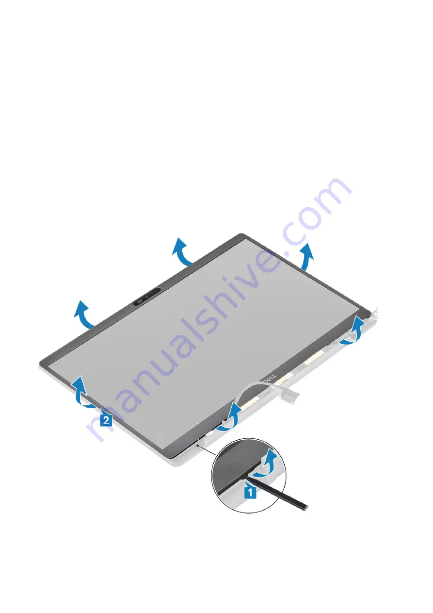
1. Use a plastic scribe to pry at the indents on the bottom of display assembly beside the hinges [1].
2. Pry along the outer edges of display bezel to remove the bezel from the display assembly [2].

Removing and installing components

61

Summary of Contents for Inspiron 7400

Page 1: ...Dell Latitude 7400 Service Manual Regulatory Model P100G Regulatory Type P100G001 September 2021 Rev A04 ...

Page 2: ...tial damage to hardware or loss of data and tells you how to avoid the problem WARNING A WARNING indicates a potential for property damage personal injury or death 2016 2020 Dell Inc or its subsidiaries All rights reserved Dell EMC and other trademarks are trademarks of Dell Inc or its subsidiaries Other trademarks may be trademarks of their respective owners ...

Page 3: ...the base cover 17 Installing the base cover 20 Battery 22 Lithium ion battery precautions 22 Removing the battery 22 Installing the battery 23 Coin cell 24 Removing the coin cell 24 Installing the coin cell 26 Memory 28 Removing the memory 28 Installing the memory 28 Solid state drive 29 Removing the solid state drive 29 Installing the solid state drive 31 WLAN card 32 Removing the WLAN card 32 In...

Page 4: ...g the hinges 57 Installing the hinges 59 Display Bezel 61 Removing the display bezel 61 Installing the display bezel 62 Display Panel 62 Removing the display panel 62 Installing the display panel 64 Camera microphone module 66 Removing the camera microphone module 66 Installing the camera microphone module 66 Display Cable 67 Removing the display cable 67 Installing the display cable 68 System boa...

Page 5: ...tup password 105 Assigning a system setup password 105 Deleting or changing an existing system setup password 105 Clearing CMOS settings 106 Clearing BIOS System Setup and System passwords 106 Chapter 6 Troubleshooting 107 Handling swollen Lithium ion batteries 107 Dell SupportAssist Pre boot System Performance Check diagnostics 108 Running the SupportAssist Pre Boot System Performance Check 108 B...

Page 6: ... a card by its edges or by its metal mounting bracket Hold a component such as a processor by its edges not by its pins CAUTION When you disconnect a cable pull on its connector or on its pull tab not on the cable itself Some cables have connectors with locking tabs if you are disconnecting this type of cable press in on the locking tabs before you disconnect the cable As you pull connectors apart...

Page 7: ...secure and in full contact with your skin and ensure that you remove all jewelry such as watches bracelets or rings prior to bonding yourself and the equipment Electrostatic discharge ESD protection ESD is a major concern when you handle electronic components especially sensitive components such as expansion cards processors memory DIMMs and system boards Very slight charges can damage circuits in...

Page 8: ...est once per week A wrist strap tester is the best method for doing this test If you do not have your own wrist strap tester check with your regional office to find out if they have one To perform the test plug the wrist strap s bonding wire into the tester while it is strapped to your wrist and push the button to test A green LED is lit if the test is successful a red LED is lit and an alarm soun...

Page 9: ...t your back 4 Keep the load close The closer it is to your spine the less force it exerts on your back 5 Keep your back upright whether lifting or setting down the load Do not add the weight of your body to the load Avoid twisting your body and back 6 Follow the same techniques in reverse to set the load down After working inside your computer NOTE Leaving stray or loose screws inside your compute...

Page 10: ...ter than its predecessor In a nutshell USB 3 1 Gen 1 features are as follows Higher transfer rates up to 5 Gbps Increased maximum bus power and increased device current draw to better accommodate power hungry devices New power management features Full duplex data transfers and support for new transfer types Backward USB 2 0 compatibility New connectors and cable The topics below cover some of the ...

Page 11: ...tive it s easy to imagine that with 5 10 times the bandwidth available USB video solutions should work that much better Single link DVI requires almost 2Gbps throughput Where 480Mbps was limiting 5Gbps is more than promising With its promised 4 8Gbps speed the standard will find its way into some products that previously weren t USB territory like external RAID storage systems Listed below are som...

Page 12: ...se portable battery packs you charge your smartphones and other portable devices from today You could plug your laptop into an external display connected to a power cable and that external display would charge your laptop as you used it as an external display all via the one little USB Type C connection To use this the device and the cable have to support USB Power Delivery Just having a USB Type ...

Page 13: ...interface HDMI provides an interface between any compatible digital audio video source such as a DVD player or A V receiver and a compatible digital audio and or video monitor such as a digital TV DTV The primary advantage is cable reduction and content protection provisions HDMI supports standard enhanced or high definition video plus multichannel digital audio on a single cable HDMI 1 4a Feature...

Page 14: ... quality and functionality of a digital interface while also supporting uncompressed video formats in a simple cost effective manner Audio HDMI supports multiple audio formats from standard stereo to multichannel surround sound HDMI combines video and multichannel audio into a single cable eliminating the cost complexity and confusion of multiple cables currently used in A V systems HDMI supports ...

Page 15: ...Major components of your system 1 Base cover 2 Power adaptor port 3 Major components of your system 15 ...

Page 16: ...oard 13 Display assembly 14 Palmrest assembly 15 WLAN card 16 WWAN card NOTE Dell provides a list of components and their part numbers for the original system configuration purchased These parts are available according to warranty coverages purchased by the customer Contact your Dell sales representative for purchase options 16 Major components of your system ...

Page 17: ...apter port Speakers LED board Touchpad button board Smart card reader Display assembly Hinge caps Display hinges Display Bezel Display Panel Camera microphone module Display Cable System board Power Button Board Keyboard Palmrest Base cover Removing the base cover Follow the procedure in before working inside your computer 1 Loosen the eight captive screws that secure the base cover to the compute...

Page 18: ...2 Use a plastic scribe to pry the base cover at the indents near the left and right hinges 1 3 Work along the edges to separate the base cover from the computer 2 18 Removing and installing components ...

Page 19: ...4 Lift and remove the base cover from the computer Removing and installing components 19 ...

Page 20: ...Installing the base cover 1 Align and place the base cover on the computer 2 Press along the edges of the base cover until it clicks into the palmrest assembly 20 Removing and installing components ...

Page 21: ...3 Tighten the eight captive screws to secure the base cover to the computer Removing and installing components 21 ...

Page 22: ...r system components If the battery gets stuck inside your computer as a result of swelling do not try to release it as puncturing bending or crushing a lithium ion battery can be dangerous In such an instance contact Dell technical support for assistance See www dell com contactdell Always purchase genuine batteries from www dell com or authorized Dell partners and resellers Swollen batteries shou...

Page 23: ...2 Tighten the two captive screws 2 to secure the battery 4 Cell to the computer NOTE A 3 Cell battery has single captive screw that secures the battery to the computer 3 Connect the battery cable to its connector on the system board 3 Removing and installing components 23 ...

Page 24: ...he coin cell 1 Follow the procedure in before working inside your computer 2 Remove the base cover 3 Remove the battery 1 Disconnect the LED daughterboard cable from the connector on the system board 1 2 Peel back the LED daughterboard cable from over the coin cell 2 24 Removing and installing components ...

Page 25: ...3 Disconnect the coin cell cable from the connector on the system board 1 4 Remove the coin cell from the computer 2 Removing and installing components 25 ...

Page 26: ...Installing the coin cell 1 Connect the coin cell cable to its connector on the system board 1 and adhere the coin cell to the palmrest 2 26 Removing and installing components ...

Page 27: ...2 Connect the LED board cable to the system board 1 and route the ribbon cable over the coin cell 2 Removing and installing components 27 ...

Page 28: ... before working inside your computer 2 Remove the base cover 3 Remove the battery 1 Pry the clips securing the memory module until the memory module pops up 1 2 Lift the memory module away from the connector 2 Installing the memory Insert the memory module on the memory connector until the clips secure the memory module 28 Removing and installing components ...

Page 29: ...dure in before working inside your computer 2 Remove the base cover 3 Remove the battery 1 NOTE This procedure illustrates a M 2 2280 SSD M 2 2230 SSD is secured to the palmrest with special bracket and plate Loosen the three captive screws that secure the SSD bracket to the palmrest 1 2 Remove the SSD plate from the top of the SSD 2 Removing and installing components 29 ...

Page 30: ...3 Slightly lift and remove the SSD out from its connector on the system board 30 Removing and installing components ...

Page 31: ...lot and slide it to its connector on the system board 2 Place the SSD plate pre installed with thermal sticker on the underside over the SSD 1 3 Tighten the three captive screws to secure the SSD bracket to the palmrest 2 Removing and installing components 31 ...

Page 32: ...he WLAN card 1 Follow the procedure in before working inside your computer 2 Remove the base cover 3 Remove the battery 1 Remove the single M2x3 screw that secures the metal bracket to the WLAN card 1 2 Remove the metal bracket from over the WLAN card antennae connector 2 3 Disconnect the WLAN antennae cables from its connectors on the WLAN card 3 4 Sightly lift and slide the WLAN card from the sl...

Page 33: ...tem board 1 2 Connect the antennae cables to the connectors on the WLAN card 2 3 Place the metal bracket over the antennae connectors 3 4 Replace the single M2x3 screw to secure the metal bracket to the WLAN card and the system board 4 Removing and installing components 33 ...

Page 34: ...before working inside your computer 2 Remove the base cover 3 Remove the battery 1 Remove the single M2x3 screw that secures the metal bracket to the WWAN card 1 2 Remove the metal bracket 2 and disconnect the antennae cables from the connectors on the WWAN card 3 3 Remove the WWAN card from its connector on the system board 4 34 Removing and installing components ...

Page 35: ...board 1 2 Connect the antennae cables to the connectors on WWAN card 2 3 Place the metal bracket over the antennae connectors on the WWAN card 3 4 Replace the single M2x3 screw to secure the metal bracket to the WWAN card and the system board 4 Removing and installing components 35 ...

Page 36: ...2 Remove the base cover 3 Remove the battery 4 Remove the WWAN card 1 NOTE Heatsink and Fan are separately orderable parts Disconnect the fan cable from the connector on the system board 1 2 Remove the two M2x3 screws in sequence 2 1 on the fan case and four M2x3 screws in sequence 4 3 2 1 from the heatsink 2 3 Lift and remove the heatsink fan assembly from the computer 3 36 Removing and installin...

Page 37: ...e screw securing the fan to heatsink Installing the heatsink assembly 1 NOTE Heatsink and Fan are separately orderable parts Install the single screw securing the fan to the heatsink Removing and installing components 37 ...

Page 38: ...1 on fan case and four M2x3 screws in sequence 4 3 2 1 on the heatsink fan assembly 1 4 Connect the fan cable to the system board 2 1 Install the WWAN card 2 Install the battery 3 Install the base cover 4 Follow the procedure after working inside your computer 38 Removing and installing components ...

Page 39: ...apter port 1 2 Remove the metal bracket that secures the power adapter port 2 3 Disconnect the power adapter port cable from the system board 1 4 Lift and remove the power adapter port from its slot in the palmrest 2 Installing the power adapter port 1 Connect the power adapter port cable to its connector on the system board 1 2 Place the power adapter port into its slot on the palmrest 2 Removing...

Page 40: ...orking inside your computer Speakers Removing the speakers 1 Follow the procedure in before working inside your computer 2 Remove the base cover 3 Remove the battery 1 Disconnect the speaker cable from its connector on the system board 1 2 Unroute the speaker cable from the routing channel near the coin cell 2 3 Peel back the tape securing the speaker cable to the touchpad button board 3 40 Removi...

Page 41: ...4 Remove the four M2x3 screws securing the speakers to the palmrest assembly 1 5 Lift and remove the speakers from the palmrest assembly 2 Removing and installing components 41 ...

Page 42: ...Installing the speakers 1 Align and place the speakers into the palmrest assembly 1 2 Replace the four M2x3 screws to secure the speakers to the palmrest assembly 2 42 Removing and installing components ...

Page 43: ...ere the tape to secure the speaker cable on the touchpad button board 1 4 Route the speaker cable 2 and connect the speaker cable to the connector on the system board 3 Removing and installing components 43 ...

Page 44: ... daughterboard 1 Follow the procedure in before working inside your computer 2 Remove the base cover 3 Remove the battery 1 Disconnect the LED board ribbon cable from the connector on the system board 1 2 Remove the single M2x3 screw 2 and lift the LED daughterboard from the palmrest assembly 3 44 Removing and installing components ...

Page 45: ...lace the LED daughterboard on the palmrest assembly 1 2 Replace the single M2x3 screw securing the LED daughterboard to the palmrest assembly 2 3 Connect the LED daughterboard ribbon cable to the system board 3 Removing and installing components 45 ...

Page 46: ... Follow the procedure in before working inside your computer 2 Remove the base cover 3 Remove the battery 4 Remove the speaker 1 Disconnect the touchpad button board cable from the touchpad module 1 2 Remove the two M2x2 5 screws that secures touchpad button board to the palmrest assembly 2 3 Remove the touchpad button board from the palmrest assembly 3 46 Removing and installing components ...

Page 47: ...1 Place the touchpad button board on the palmrest assembly 1 2 Replace the two M2x2 5 screws to secure it to the palmrest assembly 2 3 Connect the touch pad button board cable to the touchpad module 3 Removing and installing components 47 ...

Page 48: ...ing inside your computer 2 Remove the base cover 3 Remove the battery 4 Remove the SSD 5 Remove the speaker 1 Disconnect the smart card reader cable from the USH board 1 2 Disconnect the touchpad button cable from the tocuhpad module 2 3 Remove the four M2x2 5 screws securing the smart card reader to the palmrest assembly 3 4 Remove the smart card reader from the computer 4 48 Removing and install...

Page 49: ... its slot on the palmrest assembly 1 2 Replace the four M2x2 5 screws securing it to the palmrest assembly 2 3 Connect the touchpad button board cable to the touchpad module 3 4 Connect the smart card reader cable to the USH board 4 Removing and installing components 49 ...

Page 50: ...the display assembly 1 Follow the procedure in before working inside your computer 2 Remove the base cover 3 Remove the battery 1 Remove the single M2x4 screw 1 that secures the display cable metal bracket to the system board 2 Lift and remove the metal bracket 2 to disconnect the display cable from the connector on the system board 3 50 Removing and installing components ...

Page 51: ...3 Lift the display cable 1 and unroute it from the metal bracket on the system board 2 4 Open the display lid 180 degrees Removing and installing components 51 ...

Page 52: ...5 Remove the six M2 5x4 screws 1 and remove the display assembly from the palmrest assembly 2 52 Removing and installing components ...

Page 53: ... display assembly aligning the screw holes on the hinges with the screw holes on the palmrest assembly 1 2 Replace the six M2 5x3 5 screws 2 to secure the display assembly to the computer 2 3 Close the LCD lid Removing and installing components 53 ...

Page 54: ...it on the system board 2 5 Connect the display cable to the connector on the system board 1 6 Install the display cable metal bracket 2 above the display cable connector and secure it the system board using a single M2x3 screw 3 54 Removing and installing components ...

Page 55: ...inge cap 1 Follow the procedure in before working inside your computer 2 Remove the base cover 3 Remove the battery 4 Remove the display assembly 1 Open the hinges to 90 degrees to the display assembly 1 2 Slide the hinge cap towards the right hinge and lift it away from the display assembly 2 Removing and installing components 55 ...

Page 56: ...ling the hinge cap 1 Slide the hinge cap towards the left hinge until it click locks on the display assembly 1 2 Close the hinges to 180 degrees to the display assembly 2 56 Removing and installing components ...

Page 57: ... inside your computer Display hinges Removing the hinges 1 Follow the procedure in before working inside your computer 2 Remove the base cover 3 Remove the battery 4 Remove the display assembly 5 Remove the hinge cap 1 Unroute the antennae and display cable away from the hinges Removing and installing components 57 ...

Page 58: ...2 Remove the four M2 5x5 screws 1 securing the hinges to the display assembly 3 Lift and remove the hinges from the display back cover assembly 2 58 Removing and installing components ...

Page 59: ...Installing the hinges 1 Align and place the hinges on the display assembly 1 2 Replace the four 2 5x5 screws to secure hinges to the display back cover assembly 2 Removing and installing components 59 ...

Page 60: ...3 Route the antennae and display cable along the hinges 60 Removing and installing components ...

Page 61: ...ollow the procedure in before working inside your computer 2 Remove the base cover 3 Remove the battery 4 Remove the display assembly 5 Remove the hinge cap 6 Remove the hinges 1 Use a plastic scribe to pry at the indents on the bottom of display assembly beside the hinges 1 2 Pry along the outer edges of display bezel to remove the bezel from the display assembly 2 Removing and installing compone...

Page 62: ...se cover 6 Follow the procedure after working inside your computer Display Panel Removing the display panel 1 Follow the procedure in before working inside your computer 2 Remove the base cover 3 Remove the battery 4 Remove the display assembly 5 Remove the hinge cap 6 Remove the hinges 7 Remove the display bezel 1 Remove the four M2x2 5 screws 1 and flip over display panel 2 to separate the LCD p...

Page 63: ...etch SR tapes from the display panel There is no need to separate the brackets from the display panel Peel back the tape 1 and flip open the latch 2 to disconnect the EDP cable from the display panel 3 Removing and installing components 63 ...

Page 64: ...e to the connector on the display panel 1 and close the actuator to secure the connector 2 2 Adhere the adhesive tape over the EDP connector on the display panel 3 and flip over the display panel on the back cover 4 64 Removing and installing components ...

Page 65: ...3 Install the four M2x2 5 screws 2 on the display panel to secure it to the back cover Removing and installing components 65 ...

Page 66: ...base cover 3 Remove the battery 4 Remove the display assembly 5 Remove the hinge cap 6 Remove the hinges 7 Remove the display bezel 8 Remove the display panel 1 Disconnect the display cable connection from the camera microphone module 1 2 Use a plastic scribe to pry the camera microphone module from the display back cover 2 Installing the camera microphone module 1 Align and place the camera micro...

Page 67: ...display cable 1 Follow the procedure in before working inside your computer 2 Remove the base cover 3 Remove the battery 4 Remove the display assembly 5 Remove the hinge cap 6 Remove the display bezel 7 Remove the hinges 8 Remove the display panel 1 Peel back the adhesive tape securing the display cable to the camera microphone module 1 2 Gently peel off the display cable from its routing channel ...

Page 68: ...e 1 Adhere the display cable along the routing channel on the display back cover assembly 1 2 Connect the display cable to the camera microphone module and replace the tape on the connector 2 68 Removing and installing components ...

Page 69: ...he battery 4 Remove the memory 5 Remove the SSD 6 Remove the WLAN card 7 Remove the heatsink fan assembly 8 Remove the power adapter port 9 Remove the display assembly NOTE System board can be removed with heatsink assembly installed this simplifies the procedure in an event of power button keyboard and palmrest assembly replacements 1 Remove the single M2x4 screw on the metal bracket over the dis...

Page 70: ...2 4 Remove the single M2x4 screw 1 and remove the metal bracket over the WWAN Darwin antennae cable 2 5 Disconnect the power button with finger print reader cable from the system board 1 6 Disconnect the WWAN Darwin antennae cables 2 from the system board 70 Removing and installing components ...

Page 71: ...two M2x4 screws 1 and lift up the USB Type C bracket from the system board 2 8 Disconnect the coin cell 1 speaker cable 2 and the LED daughterboard cable 3 from the system board Removing and installing components 71 ...

Page 72: ...9 Disconnect the USH daughterboard 1 and touchpad cables 2 from the system board 72 Removing and installing components ...

Page 73: ...10 Remove the two M2x2 5 screws on the DDR ESD bracket 1 and lift to remove it from the system board 2 Removing and installing components 73 ...

Page 74: ... and remove the system board from the palmrest assembly 2 NOTE For models shipped with a fingerprint reader or WWAN antennas there are three M2x3 screws securing the system board to the computer 74 Removing and installing components ...

Page 75: ...ing the system board 1 Align and place the system board in the palmrest assembly 1 2 Replace the two M2x4 screws on the system board securing it to the palmrest assembly 2 Removing and installing components 75 ...

Page 76: ...uring the system board to the computer 3 Place the USB Type C bracket 1 on the system board and secure it using two M2x5 screws 2 to the system board 4 Install the DDR ESD bracket 1 on the system board and secure it using two M2x2 5 screws to the system board 2 76 Removing and installing components ...

Page 77: ...5 Open the latch and connect the USH board cable 1 and the touchpad cable 2 to the system board Removing and installing components 77 ...

Page 78: ...6 Connect the coin cell 1 speaker cable 2 and the LED daughterboard ribbon cable 3 to the system board 78 Removing and installing components ...

Page 79: ...n the Darwin connector 1 and secure it to the palmrest using a single M2x4 screw 2 to the system board 8 Route the display cable through the metal bracket 1 and connect it to the system board 2 Removing and installing components 79 ...

Page 80: ...ngle M2x3 screw 2 10 Connect the power button with finger print reader cable to the system board 1 11 Connect the Darwin WWAN antenna cables 2 to the the system board 1 Install the display assembly 2 Install the power adapter port 3 Install the heatsink fan assembly 80 Removing and installing components ...

Page 81: ...attery 4 Remove the memory 5 Remove the SSD 6 Remove the WLAN card 7 Remove the heatsink fan assembly 8 Remove the power adapter port 9 Remove the speaker 10 Remove the display assembly 11 Remove the system board 1 Remove the two M2x2 5 screws that secure the power button board to the palmrest assembly 1 2 Remove the power button board from its slot in the palmrest assembly 2 NOTE Power button boa...

Page 82: ...Figure 3 Power button board without FPR 82 Removing and installing components ...

Page 83: ...PR Installing the power button board 1 Align and place the power button board in to its slot on the plamrest assembly 1 2 Replace the two M2x2 5 screws to secure the power button board to the palmrest assembly 2 Removing and installing components 83 ...

Page 84: ...Figure 5 Power button board without FPR 84 Removing and installing components ...

Page 85: ...r adapter port 5 Install the heatsink fan assembly 6 Install the WLAN card 7 Install the SSD 8 Install the memory 9 Install the battery 10 Install the base cover 11 Follow the procedure after working inside your computer Keyboard Removing the keyboard 1 Follow the procedure in before working inside your computer 2 Remove the base cover 3 Remove the battery 4 Remove the memory 5 Remove the SSD 6 Re...

Page 86: ... cable 1 and the backlight cable 2 from the touchpad module 2 NOTE This image shows disassembly of a carbon fiber variant an Aluminum variant of this model has 21 M1 6x2 screws securing the keyboard assembly to palmrest Remove the 19 M1 6x2 screws 3 and separate the keyboard assembly from the palmrest 4 3 Remove the five M2x2 screws 1 to lift the keyboard from the keyboard support plate 86 Removin...

Page 87: ...t keyboard Align the keyboard to the keyboard support plate 1 and replace the two M2x2 screws 2 2 Place the keyboard assembly in the palmrest 1 and secure it with the 17 M1 6x2 screws 2 NOTE This image shows disassembly of a carbon fiber variant an Aluminum variant of this model has 21 M1 6x2 screws securing the keyboard assembly to palmrest assembly Removing and installing components 87 ...

Page 88: ...he WLAN card 8 Install the SSD 9 Install the memory 10 Install the battery 11 Install the base cover 12 Follow the procedure after working inside your computer Palmrest 1 Follow the procedure in before working inside your computer 2 Remove the base cover 3 Remove the battery 4 Remove the memory 5 Remove the SSD 6 Remove the WLAN card 7 Remove the heatsink fan assembly 8 Remove the power adapter po...

Page 89: ...nts to the new palmrest assembly 1 Install the keyboard 2 Install the power button 3 Install the coin cell 4 Install the system board 5 Install the display assembly 6 Install the speaker 7 Install the LED board 8 Install the power adapter port 9 Install the heatsink fan assembly 10 Install the WLAN card 11 Install the SSD 12 Install the memory 13 Install the battery 14 Install the base cover 15 Fo...

Page 90: ...ering BIOS setup program Navigation keys One time boot menu System setup options Updating the BIOS System and setup password Clearing CMOS settings Clearing BIOS System Setup and System passwords BIOS overview The BIOS manages data flow between the computer s operating system and attached devices such as hard disk video adapter keyboard mouse and printer Entering BIOS setup program 1 Turn on your ...

Page 91: ... on The one time boot menu displays the devices that you can boot from including the diagnostic option The boot menu options are Removable Drive if available STXXXX Drive if available NOTE XXX denotes the SATA drive number Optical Drive if available SATA Hard Drive if available Diagnostics The boot sequence screen also displays the option to access the System Setup screen System setup options NOTE...

Page 92: ...hnology Device Information M 2 SATA M 2 SATA1 M 2 PCIe SSD 0 M 2 PCIe SSD 1 Passthrough MAC Address Video Controller Video BIOS Version Video Memory Panel Type Native Resolution Privacy Screen NOTE Applicable for e Privacy version Audio Controller Wi Fi Device Bluetooth Device Battery Information Displays the battery status and the type of AC adapter connected to the computer Boot Sequence Allows ...

Page 93: ...d to support RAID mode Drives These fields let you enable or disable various drives on board The options are SATA 1 SATA 2 M 2 PCIe SSD 0 M 2 PCIe SSD 1 SMART Reporting This field controls whether hard drive errors for integrated drives are reported during startup The option is disabled by default USB Configuration Allows you to enable or disable the internal integrated USB configuration The optio...

Page 94: ... is disabled NOTE A reboot is required for these changes to take effect USB PowerShare This option enable disable the USB PowerShare feature behavior This option is disabled by default Audio Allows you to enable or disable the integrated audio controller By default the Enable Audio option is selected The options are Enable Microphone Enable Internal Speaker This option is set by default Keyboard I...

Page 95: ...he Fingerprint Reader or the Fingerprint Reader Device s Single Sign On capability Enable Fingerprint Reader Device Enabled by Default NOTE Option present on system opted with finger print reader on the power button Miscellaneous devices Allows you to enable or disable various on board devices Enable Camera Default Enable Secure Digital SD Card Secure Digital SD Card Boot Disabled Secure Digital C...

Page 96: ...assword Click OK once you set the password NOTE For the first time login Enter the old password field is marked to Not set Hence password has to be set for the first time you log in and then you can change or delete the password System Password Allows you to set change or delete the System password The entries to set password are Enter the old password Enter the new password Confirm new password C...

Page 97: ...Clear Command Attestation Enable Default Key Storage Enable Default SHA 256 Default Absolute This field lets you Enable Disable or Permanently Disable the BIOS module interface of the optional Absolute Persistence Module service from Absolute Software This option is enabled by default OROM Keyboard Access This option determines whether users are able to enter Option ROM Configuration screens via h...

Page 98: ...ent Allows you to enable or disable Expert Key Management Enable Custom Mode This option is not set by default The Custom Mode Key Management options are PK Default KEK db dbx Intel Software Guard Extensions options Table 8 Intel Software Guard Extensions Option Description Intel SGX Enable This field specifies you to provide a secured environment for running code storing sensitive information in ...

Page 99: ...the processor Hyper Thread Control Allows you to enable or disable the HyperThreading in the processor Disabled Enabled Default Power management Table 10 Power Management Option Description AC Behavior Allows you to enable or disable the computer from turning on automatically when an AC adapter is connected Wake on AC This option is not set by default Enable Intel Speed Shift technology This optio...

Page 100: ... health By enabling this option your system uses the standard charging algorithm and other techniques during the non work hours to improve the battery health Advanced Battery Charge Mode can be configured for all weekdays Primary Battery Charge Configuration Allows you to select the charging mode for the battery The options are Adaptive Default Standard Fully charges your battery at a standard rat...

Page 101: ... Allows you to display full screen logo if your image matches screen resolution Enable Full Screen Logo This option is not set by default Warnings and Errors Allows you to select different options to either stop prompt and wait for user input continue when warnings are detected but pause on errors or continue when either warnings or errors are detected during the POST process Click one of the foll...

Page 102: ...on is set by default Trusted Execution This option specifies whether a Measured Virtual Machine Monitor MVMM can utilize the additional hardware capabilities provided by Intel Trusted Execution Technology NOTE The TPM has to be enabled and activated and Virtualization Technology and VT for Direct I O must be enabled to use this feature Wireless options Table 14 Wireless Option Description Wireless...

Page 103: ... system it will not recognize the BitLocker key You will then be prompted to enter the recovery key to progress and the system will ask for this on each reboot If the recovery key is not known this can result in data loss or an unnecessary operating system re install For more information on this subject see Knowledge Article https www dell com support article sln153694 1 Go to www dell com support...

Page 104: ...s not suspended before updating the BIOS the next time you reboot the system it will not recognize the BitLocker key You will then be prompted to enter the recovery key to progress and the system will ask for this on each reboot If the recovery key is not known this can result in data loss or an unnecessary operating system re install For more information on this subject see Knowledge Article http...

Page 105: ...he status is in Not Set To enter the system setup press F12 immediately after a power on or reboot 1 In the System BIOS or System Setup screen select Security and press Enter The Security screen is displayed 2 Select System Admin Password and create a password in the Enter the new password field Use the following guidelines to assign the system password A password can have up to 32 characters At l...

Page 106: ...up The computer restarts Clearing CMOS settings CAUTION Clearing CMOS settings will reset the BIOS settings on your computer 1 Remove the base cover 2 Disconnect the battery cable from the system board 3 Remove the coin cell battery 4 Wait for one minute 5 Replace the coin cell battery 6 Connect the battery cable to the system board 7 Replace the base cover Clearing BIOS System Setup and System pa...

Page 107: ...harge the battery unplug the AC adapter from the system and operate the system only on battery power When the system will no longer power on when the power button is pressed the battery is fully discharged Do not crush drop mutilate or penetrate the battery with foreign objects Do not expose the battery to high temperatures or disassemble battery packs and cells Do not apply pressure to the surfac...

Page 108: ...s 3 On the boot menu screen select the Diagnostics option 4 Click the arrow at the bottom left corner Diagnostics front page is displayed 5 Click the arrow in the lower right corner to go to the page listing The items detected are listed 6 To run a diagnostic test on a specific device press Esc and click Yes to stop the diagnostic test 7 Select the device from the left pane and click Run Tests 8 I...

Page 109: ...For cases when a 2 8 error code is shown replace the system board LCD Built in Self Test BIST Dell laptops have a built in diagnostic tool that helps you determine if the screen abnormality you are experiencing is an inherent problem with the LCD screen of the Dell laptop or with the video card GPU and PC settings When you notice screen abnormalities like flickering distortion clarity issues fuzzy...

Page 110: ...m troubleshooting and repairs as authorized or directed by the Dell technical assistance team Damage due to servicing that is not authorized by Dell is not covered by your warranty Table 19 Diagnostic light LED codes Diagnostic light codes Amber White Problem description 2 1 Processor failure 2 2 System board BIOS or ROM Read Only Memory failure 2 3 No memory or RAM Random Access Memory detected 2...

Page 111: ...ff your computer 2 Turn off the modem 3 Turn off the wireless router 4 Wait for 30 seconds 5 Turn on the wireless router 6 Turn on the modem 7 Turn on your computer Drain residual flea power perform hard reset Flea power is the residual static electricity that remains in the computer even after it has been powered off and the battery is removed For your safety and to protect the sensitive electron...

Page 112: ...e based support and service options Availability varies by country and product and some services may not be available in your area To contact Dell for sales technical support or customer service issues 1 Go to Dell com support 2 Select your support category 3 Verify your country or region in the Choose a Country Region drop down list at the bottom of the page 4 Select the appropriate service or su...

Reviews: