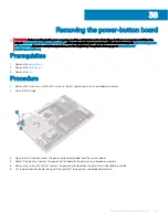
Removing the system board
WARNING:
Before working inside your computer, read the safety information that shipped with your computer and follow the
steps in
Before working inside your computer
. After working inside your computer, follow the instructions in
. For more safety best practices, see the Regulatory Compliance home page at
NOTE:
Your computer’s Service Tag is stored in the system board. You must enter the Service Tag in the BIOS setup program
after you replace the system board.
NOTE:
Replacing the system board removes any changes you have made to the BIOS using the BIOS setup program. You must
make the appropriate changes again after you replace the system board.
NOTE:
Before disconnecting the cables from the system board, note the location of the connectors so that you can reconnect
the cables correctly after you replace the system board.
Prerequisites
1
Remove the
.
2
Remove the
3
Remove the
4
Remove the
.
5
Remove the
6
Remove the
solid-state drive/Intel Optane
.
7
Remove the
.
8
Remove the
.
Procedure
1
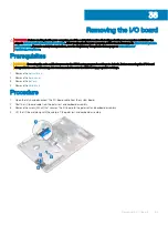
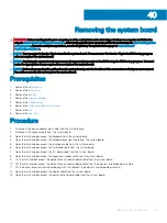
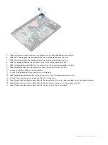
Disconnect the power-adapter port cable from the system board.
2
Disconnect the speaker cable from the system board.
3
Open the latch and disconnect the keyboard from the system board.
4
Open the latch and disconnect the keyboard back-light cable from the system board.
5
Open the latch and disconnect the touchpad cable from the system board.
6
Open the latch and disconnect the hard-drive cable from the system board.
7
Open the latch and disconnect the I/O board cable from the system board.
8
Open the latch and disconnect the finger-print reader cable from the system board.
9
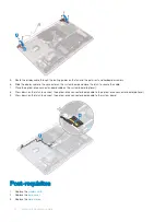
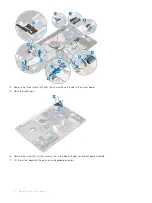
Lift the latch and disconnect the optical-drive connector-board cable from the system board .
10 Lift the latch and disconnect the optical-drive connector-board cable from the palm rest and keyboard assembly .
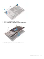
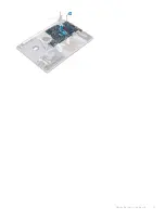
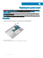
11 Lift the optical-drive connector board along with the cable off the palm rest and keyboard assembly (.
12 Open the latch and disconnect the display cable from the system board.
13 Open the latch and disconnect the power-button board cable from the system board.
40
Removing the system board
69
Summary of Contents for Inspiron 3580
Page 1: ...Inspiron 3580 Service Manual Regulatory Model P75F Regulatory Type P75F106 ...
Page 18: ...18 Removing the optical drive ...
Page 20: ...20 Replacing the optical drive ...
Page 24: ...Post requisites Replace the optical drive 24 Replacing the base cover ...
Page 26: ...26 Removing the battery ...
Page 28: ...Post requisites 1 Replace the base cover 2 Replace the optical drive 28 Replacing the battery ...
Page 32: ...32 Removing the wireless card ...
Page 39: ...Removing the fan 39 ...
Page 41: ...Post requisites 1 Replace the base cover 2 Replace the optical drive Replacing the fan 41 ...
Page 49: ...Removing the touchpad 49 ...
Page 60: ...60 Removing the display assembly ...
Page 66: ...66 Removing the power button board ...
Page 71: ...Removing the system board 71 ...
Page 76: ...76 Removing the power button with fingerprint reader ...
Page 78: ...9 Replace the optical drive 78 Replacing the power button with fingerprint reader ...
Page 80: ...80 Removing the palm rest and keyboard assembly ...
Page 88: ...88 Removing the display panel ...

