background image

Installing the I/O board

Prerequisites

If you are replacing a component, remove the existing component before performing the installation process.

About this task

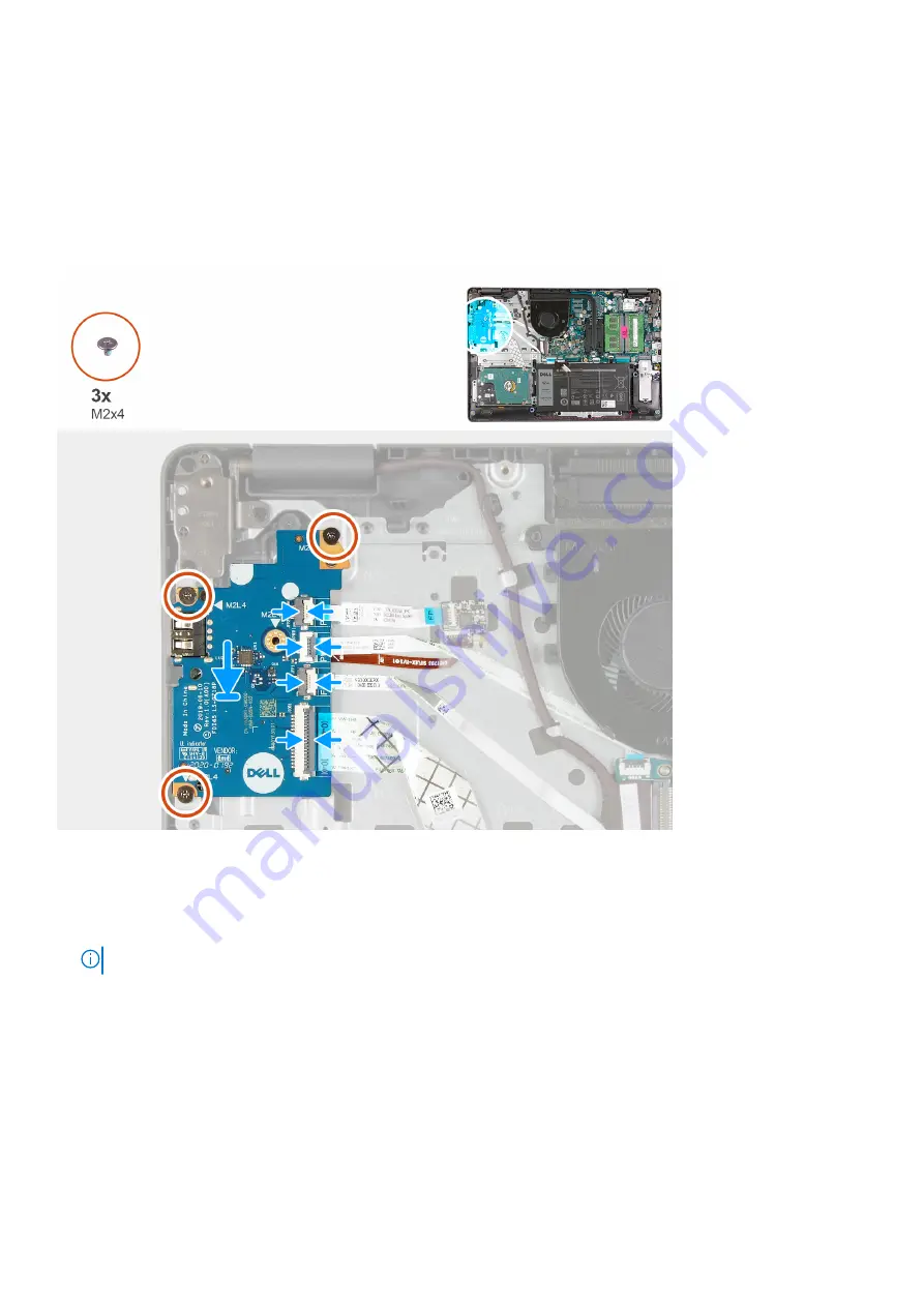
The following images indicate the location of the I/O board and provides a visual representation of the installation procedure.

Steps

1. Place the I/O board on the palm-rest and keyboard assembly.
2. Align the screw holes on the I/O board to the screw holes on the palm-rest and keyboard assembly.
3. Replace the three screws (M2x4) that secure the I/O board to the palm-rest and keyboard assembly.

NOTE:

 When replacing the screws, only replace the screws in the locations shown in the image.

4. Connect the fingerprint-reader board cable to the connector on the I/O board and close the latch, if applicable.
5. Connect the I/O-board power cable to the connector on the I/O board and close the latch.
6. Connect the fingerprint-reader cable to the connector on the I/O board and close the latch, if applicable.
7. Connect the I/O-board cable to the connector on the I/O board and close the latch.

Next steps

1. Install the 

base cover

.

2. Follow the procedure in 

After working inside your computer

.

32

Removing and installing components

Summary of Contents for Inspiron 3501

Page 1: ...Inspiron 3501 Service Manual Regulatory Model P90F Regulatory Type P90F002 August 2020 Rev A00 ...

Page 2: ...ential damage to hardware or loss of data and tells you how to avoid the problem WARNING A WARNING indicates a potential for property damage personal injury or death 2020 Dell Inc or its subsidiaries All rights reserved Dell EMC and other trademarks are trademarks of Dell Inc or its subsidiaries Other trademarks may be trademarks of their respective owners ...

Page 3: ... solid state drive 18 Removing the M 2 2280 solid state drive 19 Installing the M 2 2280 solid state drive 20 Memory modules 21 Removing the memory modules 21 Installing the memory modules 22 Wireless card 23 Removing the wireless card 23 Installing the wireless card 24 Battery 26 Lithium ion battery precautions 26 Removing the battery 26 Installing the battery 27 Hard drive 28 Removing the hard d...

Page 4: ...ling the camera 53 Touchpad 54 Removing the touchpad 54 Installing the touchpad 55 System board 56 Removing the system board 56 Installing the system board 59 Power adapter port 61 Removing the power adapter port 61 Installing the power adapter port 62 Palm rest and keyboard assembly 63 Removing the palm rest and keyboard assembly 63 Installing the palm rest and keyboard assembly 64 Chapter 3 Driv...

Page 5: ...hts 79 Recovering the operating system 80 Dell SupportAssist Pre boot System Performance Check diagnostics 80 Running the SupportAssist Pre Boot System Performance Check 80 Running the ePSA Diagnostics 81 Flea power release 81 WiFi power cycle 81 Chapter 6 Getting help and contacting Dell 83 Contents 5 ...

Page 6: ...r computer WARNING Before working inside your computer read the safety information that is shipped with your computer For more safety best practices see the Regulatory Compliance home page at www dell com regulatory_compliance WARNING Disconnect your computer from all power sources before opening the computer cover or panels After you finish working inside the computer replace all covers panels an...

Page 7: ...d to the damage The weakened trace may take weeks or months to melt and in the meantime may cause degradation of memory integrity intermittent memory errors etc The more difficult type of damage to recognize and troubleshoot is the intermittent also called latent or walking wounded failure Perform the following steps to prevent ESD damage Use a wired ESD wrist strap that is properly grounded The u...

Page 8: ... All ESD sensitive devices must be shipped and received in static safe packaging Metal static shielded bags are preferred However you should always return the damaged part using the same ESD bag and packaging that the new part arrived in The ESD bag should be folded over and taped shut and all the same foam packing material should be used in the original box that the new part arrived in ESD sensit...

Page 9: ...re that no stray screws remain inside your computer 2 Connect any external devices peripherals or cables you removed before working on your computer 3 Replace any media cards discs or any other parts that you removed before working on your computer 4 Connect your computer and all attached devices to their electrical outlets 5 Turn on your computer Working inside your computer 9 ...

Page 10: ...s are not left attached to such surface when replacing a component NOTE Screw color may vary with the configuration ordered Table 1 Screw list Component Secured to Screw type Quantity Screw image Base cover Palm rest and keyboard assembly M2 5x6 7 Base cover Palm rest and keyboard assembly Captive screw M2 5x2 5 5L 2 Battery Palm rest and keyboard assembly M2x3 3 Display panel Display assembly M2x...

Page 11: ...thermal shield Palm rest and keyboard assembly M2x2 2 1 M 2 2230 solid state drive Palm rest and keyboard assembly M2x2 1 System board Palm rest and keyboard assembly M2x4 1 Touchpad Palm rest and keyboard assembly M2x2 2 Touchpad bracket Palm rest and keyboard assembly M2x2 3 Wireless card bracket System board M2x3 1 Major components of Inspiron 3501 The following image shows the major components...

Page 12: ...ve if installed 6 M 2 2230 solid state drive if installed 7 System board 8 Memory module 9 Speakers 10 Palm rest and keyboard assembly 11 Touchpad 12 Display assembly 13 Power button with optional fingerprint reader 14 I O board 15 Coin cell battery 12 Removing and installing components ...

Page 13: ...s representative for purchase options Base cover Removing the base cover Prerequisites 1 Follow the procedure in Before working inside your computer About this task NOTE Before removing the base cover ensure that there is no micro SD card installed in the micro SD card slot on your computer The following images indicate the location of the base cover and provides a visual representation of the rem...

Page 14: ...14 Removing and installing components ...

Page 15: ...e base cover off the palm rest and keyboard assembly 5 Disconnect the battery cable from the system board and turn the computer over 6 Press and hold the power button for 15 seconds to ground the computer and drain the flea power Installing the base cover Prerequisites If you are replacing a component remove the existing component before performing the installation process About this task The foll...

Page 16: ...16 Removing and installing components ...

Page 17: ... and keyboard assembly Next steps 1 Follow the procedure in After working inside your computer Solid state drive Removing the M 2 2230 solid state drive Prerequisites 1 Follow the procedure in Before working inside your computer 2 Remove the base cover About this task NOTE This procedure applies only to computers shipped with an M 2 2230 solid state drive installed NOTE The M 2 card installed on y...

Page 18: ...e drive to the screw mount on the M 2 thermal shield 5 Lift the M 2 2230 solid state drive off the M 2 thermal shield Installing the M 2 2230 solid state drive Prerequisites If you are replacing a component remove the existing component before performing the installation process About this task NOTE This procedure applies if you are installing a M 2 2230 solid state drive NOTE The M 2 card install...

Page 19: ...oard assembly 7 Replace the screw M2x2 2 that secures the M 2 thermal shield to the palm rest and keyboard assembly 8 Tighten the captive screw that secures the M 2 thermal shield to the palm rest and keyboard assembly Next steps 1 Install the base cover 2 Follow the procedure in After working inside your computer Removing the M 2 2280 solid state drive Prerequisites 1 Follow the procedure in Befo...

Page 20: ...e from the M 2 card slot on the system board Installing the M 2 2280 solid state drive Prerequisites If you are replacing a component remove the existing component before performing the installation process About this task NOTE This procedure applies if you are installing a M 2 2280 solid state drive NOTE The M 2 card installed on your computer will depend on the configuration ordered Supported ca...

Page 21: ... keyboard assembly 6 Tighten the captive screw that secures the M 2 thermal shield to the palm rest and keyboard assembly Next steps 1 Install the base cover 2 Follow the procedure in After working inside your computer Memory modules Removing the memory modules Prerequisites 1 Follow the procedure in Before working inside your computer 2 Remove the base cover About this task NOTE Depending on the ...

Page 22: ...tem board 3 Repeat the precedure above for the second memory module if applicable Installing the memory modules Prerequisites If you are replacing a component remove the existing component before performing the installation process About this task The following images indicate the location of the memory modules and provides a visual representation of the installation procedure 22 Removing and inst...

Page 23: ...o place remove the memory module from the slot and repeat steps 1 to 3 5 Repeat the procedure above for the second memory module if applicable Next steps 1 Install the base cover 2 Follow the procedure in After working inside your computer Wireless card Removing the wireless card Prerequisites 1 Follow the procedure in Before working inside your computer 2 Remove the base cover About this task The...

Page 24: ... and remove the wireless card from the M 2 card slot on the system board Installing the wireless card Prerequisites If you are replacing a component remove the existing component before performing the installation process About this task The following images indicate the location of the wireless card and provides a visual representation of the installation procedure 24 Removing and installing comp...

Page 25: ...s card Antenna cable color Main white triangle White Auxiliary black triangle Black 2 Slide the wireless card into the M 2 card slot on the system board 3 Place the wireless card bracket on the wireless card 4 Replace the screw M2x3 that secures the wireless card bracket to the system board Next steps 1 Install the base cover 2 Follow the procedure in After working inside your computer Removing an...

Page 26: ...inst the battery Ensure any screws during the servicing of this product are not lost or misplaced to prevent accidental puncture or damage to the battery and other system components If the battery gets stuck inside your computer as a result of swelling do not try to release it as puncturing bending or crushing a lithium ion battery can be dangerous In such an instance contact Dell technical suppor...

Page 27: ... lift the battery off the palm rest and keyboard assembly Installing the battery Prerequisites If you are replacing a component remove the existing component before performing the installation process About this task The following images indicate the location of the battery and provides a visual representation of the installation procedure Removing and installing components 27 ...

Page 28: ...est and keyboard assembly 4 Connect the battery cable to the connector on the system board Next steps 1 Install the base cover 2 Follow the procedure in After working inside your computer Hard drive Removing the hard drive Prerequisites 1 Follow the procedure in Before working inside your computer 2 Remove the base cover 3 Remove the battery About this task The following images indicate the locati...

Page 29: ...e from the hard drive 5 Remove the four screws M3x3 that secure the hard drive bracket to the hard drive 6 Slide and remove the hard drive bracket from the hard drive Installing the hard drive Prerequisites If you are replacing a component remove the existing component before performing the installation process About this task The following images indicate the location of the hard drive and provid...

Page 30: ...e hard drive assembly on the palm rest and keyboard assembly 6 Align the screw holes on the hard drive assembly to the screw holes on the palm rest and keyboard assembly 7 Replace the three screws M2x3 that secure the hard drive assembly to the palm rest and keyboard assembly 8 Connect the hard drive cable to the connector on the system board Next steps 1 Install the battery 2 Install the base cov...

Page 31: ...ct the fingerprint reader board cable from the I O board if applicable 2 Open the latch and disconnect the I O board power cable from the I O board 3 Open the latch and disconnect the fingerprint reader cable from the I O board if applicable 4 Open the latch and disconnect the I O board cable from the I O board 5 Remove the three screws M2x4 that secure the I O board to the palm rest and keyboard ...

Page 32: ...4 that secure the I O board to the palm rest and keyboard assembly NOTE When replacing the screws only replace the screws in the locations shown in the image 4 Connect the fingerprint reader board cable to the connector on the I O board and close the latch if applicable 5 Connect the I O board power cable to the connector on the I O board and close the latch 6 Connect the fingerprint reader cable ...

Page 33: ... 1 Flip the I O board over 2 Push on the securing clip to release the coin cell battery from its holder on the I O board 3 Lift the coin cell battery from its holder on the I O board Installing the coin cell battery Prerequisites If you are replacing a component remove the existing component before performing the installation process About this task The following images indicate the location of th...

Page 34: ...ase cover 3 Follow the procedure in After working inside your computer Speakers Removing the speakers Prerequisites 1 Follow the procedure in Before working inside your computer 2 Remove the base cover 3 Remove the M 2 2230 solid state drive if applicable 4 Remove the M 2 2280 solid state drive if applicable About this task The following images indicate the location of the speakers and provides a ...

Page 35: ...ith its cable off the palm rest and keyboard assembly Installing the speakers Prerequisites If you are replacing a component remove the existing component before performing the installation process About this task The following images indicate the location of the speakers and provides a visual representation of the installation procedure Removing and installing components 35 ...

Page 36: ... Follow the procedure in After working inside your computer Heat sink Removing the heat sink Prerequisites 1 Follow the procedure in Before working inside your computer 2 Remove the base cover About this task NOTE The heat sink may become hot during normal operation Allow sufficient time for the heat sink to cool before you touch it NOTE For maximum cooling of the processor do not touch the heat t...

Page 37: ...stem board or the heat sink is replaced use the thermal grease provided in the kit to ensure that thermal conductivity is achieved The following images indicate the location of the heat sink and provides a visual representation of the installation procedure Steps 1 Place the heat sink on the system board 2 In sequential order 1 2 3 4 tighten the four captive screws that secure the heat sink to the...

Page 38: ...M2 5x5 that secure the fan to the palm rest and keyboard assembly 2 Disconnect the fan cable from the system board 3 Lift the fan from the palm rest and keyboard assembly Installing the fan Prerequisites If you are replacing a component remove the existing component before performing the installation process About this task The following images indicate the location of the fan and provides a visua...

Page 39: ...nstall the base cover 2 Follow the procedure in After working inside your computer Power button with optional fingerprint reader Removing the power button with optional fingerprint reader Prerequisites 1 Follow the procedure in Before working inside your computer 2 Remove the base cover 3 Remove the I O board About this task The following images indicate the location of the power button with optio...

Page 40: ...t and keyboard assembly if applicable NOTE This step is only applicable if your computer was shipped with the optional fingerprint reader 4 Lift the power button along with its cable off the palm rest and keyboard assembly Installing the power button with optional fingerprint reader Prerequisites If you are replacing a component remove the existing component before performing the installation proc...

Page 41: ...unds the power button cable to the palm rest and keyboard assembly if applicable NOTE This step is only applicable if your computer was shipped with the optional fingerprint reader Next steps 1 Install the I O board 2 Install the base cover 3 Follow the procedure in After working inside your computer Fingerprint reader board Removing the fingerprint reader board Prerequisites 1 Follow the procedur...

Page 42: ... from the fingerprint reader board 3 Slide and remove the fingerprint reader board from the securing clip on the palm rest and keyboard assembly Installing the fingerprint reader board Prerequisites If you are replacing a component remove the existing component before performing the installation process About this task The following images indicate the location of the fingerprint reader board and ...

Page 43: ...rd and close the latch Next steps 1 Install the base cover 2 Follow the procedure in After working inside your computer Display assembly Removing the display assembly Prerequisites 1 Follow the procedure in Before working inside your computer 2 Remove the base cover 3 Remove the wireless card About this task The following images indicate the location of the display assembly and provides a visual r...

Page 44: ...44 Removing and installing components ...

Page 45: ...x screws M2 5x6 that secure the display hinges to the palm rest and keyboard assembly 5 Lift the display assembly from the palm rest and keyboard assembly Installing the display assembly Prerequisites If you are replacing a component remove the existing component before performing the installation process About this task The following images indicate the location of the display assembly and provid...

Page 46: ...ly 5 Connect the display cable to the connector on the system board Next steps 1 Install the wireless card 2 Install the base cover 3 Follow the procedure in After working inside your computer Display bezel Removing the display bezel Prerequisites 1 Follow the procedure in Before working inside your computer 2 Remove the base cover 3 Remove the wireless card 4 Remove the display assembly About thi...

Page 47: ... assembly 3 Lift the display bezel from the display assembly Installing the display bezel Prerequisites If you are replacing a component remove the existing component before performing the installation process About this task The following images indicate the location of the display bezel and provides a visual representation of the installation procedure Removing and installing components 47 ...

Page 48: ... bezel and snap the display bezel in place Next steps 1 Install the display assembly 2 Install the wireless card 3 Install the base cover 4 Follow the procedure in After working inside your computer Display panel Removing the display panel Prerequisites 1 Follow the procedure in Before working inside your computer 2 Remove the base cover 3 Remove the wireless card 4 Remove the display assembly 48 ...

Page 49: ...Remove the display bezel About this task The following images indicate the location of the display panel and provides a visual representation of the removal procedure Removing and installing components 49 ...

Page 50: ...or latch to the display panel 6 Lift the display cable latch and disconect the display cable from the display panel 7 Lift the display panel off the display assembly NOTE The display brackets are shipped together with the display panel do not remove the display brackets from the display panel Installing the display panel Prerequisites If you are replacing a component remove the existing component ...

Page 51: ...Removing and installing components 51 ...

Page 52: ...lay assembly 6 Replace the six screws M2 5x2 5 that secure the display panel to the display assembly 7 Replace the two screws M2x2 5 that secure the display panel to the display assembly Next steps 1 Install the display assembly 2 Install the wireless card 3 Install the base cover 4 Follow the procedure in After working inside your computer Camera Removing the camera Prerequisites 1 Follow the pro...

Page 53: ...plastic scribe pry the camera from the display assembly 3 Lift the camera off the display assembly Installing the camera Prerequisites If you are replacing a component remove the existing component before performing the installation process About this task The following images indicate the location of the camera and provides a visual representation of the installation procedure Removing and instal...

Page 54: ...ess card 5 Install the base cover 6 Follow the procedure in After working inside your computer Touchpad Removing the touchpad Prerequisites 1 Follow the procedure in Before working inside your computer 2 Remove the base cover 3 Remove the battery About this task The following images indicate the location of the touchpad and provides a visual representation of the removal procedure 54 Removing and ...

Page 55: ...m rest and keyboard assembly 5 Peel the tape that secures the touchpad to the palm rest and keyboard assembly 6 Lift the touchpad off the palm rest and keyboard assembly Installing the touchpad Prerequisites If you are replacing a component remove the existing component before performing the installation process About this task The following images indicate the location of the touchpad and provide...

Page 56: ... Align the screw holes on the touchpad bracket to the screw holes on the palm rest and keyboard assembly 9 Replace the three screws M2x3 that secure the touchpad bracket to the palm rest and keyboard assembly 10 Connect the touchpad cable to the touchpad and close the latch Next steps 1 Install the battery 2 Install the base cover 3 Follow the procedure in After working inside your computer System...

Page 57: ... Speaker cable 3 Keyboard cable 4 Keyboard backlight cable 5 Touchpad cable 6 Battery cable 7 Hard drive cable 8 I O board cable 9 Fingerprint reader cable 10 Power button cable The following images indicate the location of the system board and provides a visual representation of the removal procedure Removing and installing components 57 ...

Page 58: ...atch and disconnect the hard drive cable from the system board if applicable 6 Open the latch and disconnect the touchpad cable from the system board 7 Open the latch and disconnect the keyboard backlight cable from the system board if applicable 8 Open the latch and disconnect the keyboard cable from the system board 9 Disconnect the speaker cable from the system board 10 Remove the screw M2x4 th...

Page 59: ...following image indicates the connectors on the system board 1 Power adapter port cable 2 Speaker cable 3 Keyboard cable 4 Keyboard backlight cable 5 Touchpad cable 6 Battery cable 7 Hard drive cable 8 I O board cable 9 Fingerprint reader cable 10 Power button cable The following images indicate the location of the system board and provides a visual representation of the installation procedure Rem...

Page 60: ...system board and close the latch 6 Connect the keyboard backlight cable to the connector on the system board and close the latch if applicable 7 Connect the touchpad cable to the connector on the system board and close the latch 8 Connect the hard drive cable to the connector on the system board and close the latch if applicable 9 Connect the I O board cable to the connector on the system board an...

Page 61: ...side your computer Power adapter port Removing the power adapter port Prerequisites 1 Follow the procedure in Before working inside your computer 2 Remove the base cover 3 Remove the M 2 2230 solid state drive if applicable 4 Remove the M 2 2280 solid state drive if applicable 5 Remove the fan 6 Remove the wireless card 7 Remove the display assembly 8 Remove the system board NOTE The system board ...

Page 62: ...r port Prerequisites If you are replacing a component remove the existing component before performing the installation process About this task The following images indicate the location of the power adapter port and provides a visual representation of the installation procedure 62 Removing and installing components ...

Page 63: ... Follow the procedure in After working inside your computer Palm rest and keyboard assembly Removing the palm rest and keyboard assembly Prerequisites 1 Follow the procedure in Before working inside your computer 2 Remove the base cover 3 Remove the M 2 2230 solid state drive if applicable 4 Remove the M 2 2280 solid state drive if applicable 5 Remove the hard drive 6 Remove the fan 7 Remove the w...

Page 64: ... and provides a visual representation of the removal procedure Steps After performing the pre requisites you are left with the palm rest and keyboard assembly Installing the palm rest and keyboard assembly Prerequisites If you are replacing a component remove the existing component before performing the installation process About this task The following images indicate the location of the palm res...

Page 65: ...fingerprint reader 4 Install the I O board 5 Install the speakers 6 Install the touchpad 7 Install the fingerprint reader board 8 Install the display assembly 9 Install the wireless card 10 Install the fan 11 Install the hard drive 12 Install the M 2 2230 solid state drive if applicable 13 Install the M 2 2280 solid state drive if applicable 14 Install the base cover 15 Follow the procedure in Aft...

Page 66: ...rivers and downloads When troubleshooting downloading or installing drivers it is recommended that you read the Dell Knowledge Based article Drivers and Downloads FAQ SLN128938 3 66 Drivers and downloads ...

Page 67: ...ling base devices Entering BIOS setup program Steps 1 Turn on your computer 2 Press F2 immediately to enter the BIOS setup program NOTE If you wait too long and the operating system logo appears continue to wait until you see the desktop Then turn off your computer and try again Navigation keys NOTE For most of the System Setup options changes that you make are recorded but do not take effect unti...

Page 68: ...computer Ownership Tag Displays the ownership tag of the computer Manufacture Date Displays the manufacture date of the computer Ownership Date Displays the ownership date of the computer Express Service Code Displays the express service code of the computer Ownership Tag Displays the ownership tag of the computer Signed Firmware Update Displays whether the signed firmware update is enabled Batter...

Page 69: ...olution of the computer Audio Controller Displays the audio controller information of the computer Wi Fi Device Displays the wireless device information of the computer Bluetooth Device Displays the Bluetooth device information of the computer LOM MAC Address Displays the LOM MAC address of the computer Table 5 System setup options Boot options menu Boot options Boot Mode Boot Mode UEFI only Displ...

Page 70: ...l hard drive optical drive and USB drive Enable External USB Ports Enables or disables USB ports to be functional in an operating system environment Miscellaneous Devices Enables or disables various onboard devices Enable Camera Enables or disables the camera Default ON Keyboard Illumination Configures the operating mode of the keyboard illumination feature Default Disabled The keyboard illuminati...

Page 71: ...able the BIOS module interface of the optional Computrace R Service from Absolute Software Intel Platform Trust Technology On Enables or disables Platform Trust Technology PTT visibility to the operating system Default ON PPI Bypass for Clear Commands Enables or disables the operating system to skip BIOS Physical Presence Interface PPI user prompts when issuing the Clear command Default OFF Clear ...

Page 72: ...ormal operation of Secure Boot Table 11 System setup options Expert Key Management menu Expert Key Management Enable Custom Mode Enables or disables the keys in the PK KEK db and dbx security key databases to be modified Default OFF Custom Mode Key Management Selects the custom values for expert key management Default PK Table 12 System setup options Performance menu Performance Intel Hyper Thread...

Page 73: ...harge Configuration from the beginning of the day to a specified work period Advanced Battery Charged maximizes battery health while still supporting heavy use during the work day Default OFF Block Sleep Blocks the computer from entering Sleep S3 mode in the operating system Default OFF NOTE If enabled the computer will not go to sleep Intel Rapid Start will be disabled automatically and the opera...

Page 74: ...countering a warning or error during boot Default Prompt on Warnings and Errors Stop prompt and wait for user input when warnings or errors are detected NOTE Errors deemed critical to the operation of the computer hardware will always halt the computer Table 16 System setup options Virtualization menu Virtualization Intel Virtualization Technology Enables the computer to run a virtual machine moni...

Page 75: ... events Default Keep BIOS Event Log Displays BIOS events Default Keep Thermal Event Log Displays Thermal events Default Keep Table 19 System setup options SupportAssist menu SupportAssist Dell Auto operating system Recovery Threshold Controls the automatic boot flow for SupportAssist System Resolution Console and for Dell operating system Recovery tool Default 2 SupportAssist operating system Reco...

Page 76: ...untu see https www dell com support article sln171755 Flashing the BIOS from the F12 One Time boot menu Update your computer BIOS using the BIOS update exe file that is copied to a FAT32 USB drive and booting from the F12 One Time boot menu About this task BIOS Update You can run the BIOS update file from Windows using a bootable USB drive or you can also update the BIOS from the F12 One Time boot...

Page 77: ... system password and a setup password to secure your computer CAUTION The password features provide a basic level of security for the data on your computer CAUTION Anyone can access the data stored on your computer if it is not locked and left unattended NOTE System and setup password feature is disabled Assigning a system setup password Prerequisites You can assign a new System or Admin Password ...

Page 78: ...s you to save the changes 4 Click EXIT to save the changes and exit from System Setup The computer restarts Clearing CMOS settings About this task CAUTION Clearing CMOS settings will reset the BIOS settings on your computer Steps 1 Remove the base cover 2 Disconnect the battery cable from the system board 3 Remove the coin cell battery 4 Wait for one minute 5 Replace the coin cell battery 6 Connec...

Page 79: ...ues until the computer is turned off indicating no memory or RAM is detected The following table shows different power and battery status light patterns and associated problems Table 21 LED codes Diagnostic light codes Problem description 2 1 Processor failure 2 2 System board BIOS or ROM Read Only Memory failure 2 3 No memory or RAM Random Access Memory detected 2 4 Memory or RAM Random Access Me...

Page 80: ...OS internally The embedded system diagnostics provides a set of options for particular devices or device groups allowing you to Run tests automatically or in an interactive mode Repeat tests Display or save test results Run thorough tests to introduce additional test options to provide extra information about the failed device s View status messages that inform you if tests are completed successfu...

Page 81: ...wn the computer 9 Press and hold the Fn key while pressing the power button and then release both 10 Repeat steps 3 7 above Flea power release About this task Flea power is the residual static electricity that remains on the computer even after it has been powered off and the battery has been removed or disconnected from the system board The following procedure provides the instructions on how to ...

Page 82: ...3 Turn off the wireless router 4 Wait for 30 seconds 5 Turn on the wireless router 6 Turn on the modem 7 Turn on your computer 82 Troubleshooting ...

Page 83: ... topic or model number and then click or tap the search icon to view the related articles Learn and know the following information about your product Product specifications Operating system Setting up and using your product Data backup Troubleshooting and diagnostics Factory and system restore BIOS information See Me and My Dell at www dell com support manuals To locate the Me and My Dell relevant...

Reviews: