background image

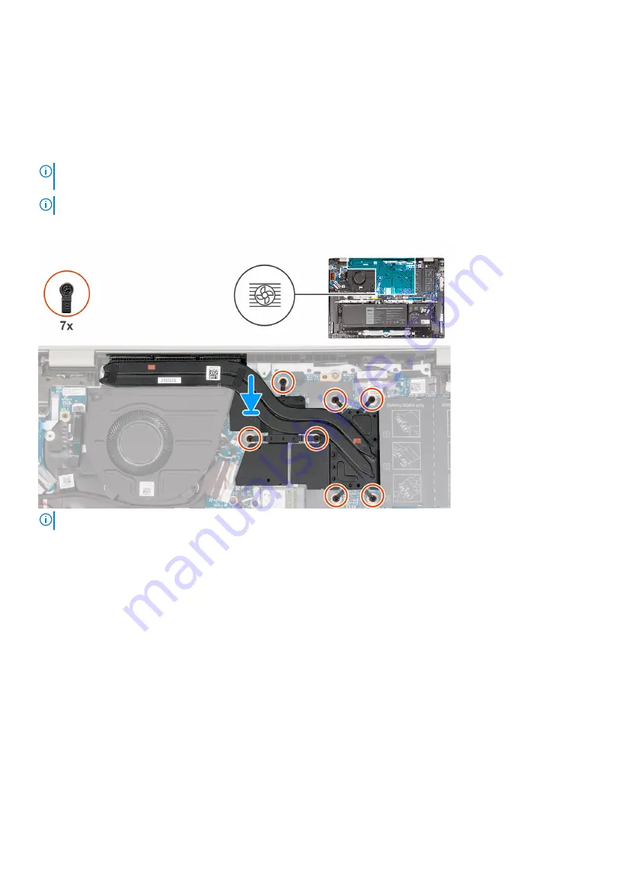
Installing the heatsink

Prerequisites

If you are replacing a component, remove the existing component before performing the installation process.

About this task

NOTE:

 If either the system board or the heat sink is replaced, use the thermal grease provided in the kit to ensure that

thermal conductivity is achieved.

NOTE:

 The number of screws on the heat sink varies depending on the graphic card configuration ordered.

The following image(s) indicate the location of the heatsink and provides a visual representation of the installation procedure.

NOTE:

 This is the heatsink for your computer that supports the 

discrete

 Graphics Processing Unit (GPU).

36

Removing and installing components

Summary of Contents for Inspiron 16 5625

Page 1: ...Inspiron 16 5625 Service Manual Regulatory Model P117F Regulatory Type P117F005 April 2022 Rev A01 ...

Page 2: ...damage to hardware or loss of data and tells you how to avoid the problem WARNING A WARNING indicates a potential for property damage personal injury or death 2022 Dell Inc or its subsidiaries All rights reserved Dell Technologies Dell and other trademarks are trademarks of Dell Inc or its subsidiaries Other trademarks may be trademarks of their respective owners ...

Page 3: ... Installing the 3 cell battery 18 Removing the 4 cell battery 19 Installing the 4 cell battery 20 Memory modules 21 Removing the memory module 21 Installing the memory module 22 Solid state drive 24 Removing the M 2 2230 solid state drive 24 Installing the M 2 2230 solid state drive 25 Removing the M 2 2280 solid state drive 26 Installing the M 2 2280 solid state drive 27 Wireless card 28 Removing...

Page 4: ...est and keyboard assembly 55 Removing the palm rest and keyboard assembly 55 Installing the palm rest and keyboard assembly 56 Chapter 3 Drivers and downloads 58 Chapter 4 BIOS setup 59 BIOS overview 59 Entering BIOS setup program 59 Navigation keys 59 One time boot menu 60 System setup options 60 System and setup password 65 Assigning a system setup password 65 Deleting or changing an existing sy...

Page 5: ...Recovering the operating system 71 Backup media and recovery options 72 WiFi power cycle 72 Drain residual flea power perform hard reset 72 Chapter 6 Getting help and contacting Dell 73 Contents 5 ...

Page 6: ...ructions that is shipped with the product or at www dell com regulatory_compliance CAUTION Before touching anything inside your computer ground yourself by touching an unpainted metal surface such as the metal at the back of the computer While you work periodically touch an unpainted metal surface to dissipate static electricity which could harm internal components CAUTION When you disconnect a ca...

Page 7: ...e through the use of a field service electrostatic discharge ESD kit When connecting a bonding wire ensure that it is connected to bare metal and never to a painted or non metal surface The wrist strap should be secure and in full contact with your skin and ensure that you remove all jewelry such as watches bracelets or rings prior to bonding yourself and the equipment Electrostatic discharge ESD ...

Page 8: ...ecommended to test the wrist strap and bonding wire at least once per week ESD Wrist Strap Tester The wires inside of an ESD strap are prone to damage over time When using an unmonitored kit it is a best practice to regularly test the strap prior to each service call and at a minimum test once per week A wrist strap tester is the best method for doing this test If you do not have your own wrist st...

Page 9: ...replacement parts or parts to be returned to Dell it is critical to place these parts in anti static bags for safe transport After working inside your computer About this task CAUTION Leaving stray or loose screws inside your computer may severely damage your computer Steps 1 Replace all screws and ensure that no stray screws remain inside your computer 2 Connect any external devices peripherals o...

Page 10: ...screw storage box This is to ensure that the correct number of screws and correct screw type is restored when the component is replaced NOTE Some computers have magnetic surfaces Ensure that the screws are not left attached to such surfaces when replacing a component NOTE Screw color may vary with the configuration ordered Table 1 Screw list Component Screw type Quantity Screw image Base cover M2x...

Page 11: ...with optional fingerprint reader M2x3 1 Power button board M2x3 1 Power button board M2x1 8 1 I O board M2x3 2 Touchpad M1 6x2 3 Touchpad M2x1 8 2 Display hinges M2 5x5 5 Major components of Inspiron 16 5625 The following image shows the major components of Inspiron 16 5625 Removing and installing components 11 ...

Page 12: ...ard 5 Battery 6 Touchpad 7 Palm rest and keyboard assembly 8 Left speaker 9 Display assembly 10 Right speaker 11 I O board 12 Wireless card bracket 13 Wireless card 14 M 2 2280 solid state drive 15 M 2 2230 solid state drive 12 Removing and installing components ...

Page 13: ...coverages purchased by the customer Contact your Dell sales representative for purchase options Base cover Removing the base cover Prerequisites 1 Follow the procedure in Before working inside your computer About this task NOTE Before removing the base cover ensure that there is no SD card installed in the SD card slot on your computer The following image s shows the base cover and provides a visu...

Page 14: ...14 Removing and installing components ...

Page 15: ...the palm rest and keyboard assembly 5 Disconnect the battery cable from the system board 6 Press and hold the power button for 20 seconds to ground the computer and drain the flea power Installing the base cover Prerequisites If you are replacing a component remove the existing component before performing the installation process About this task The following image s shows the base cover and provi...

Page 16: ...16 Removing and installing components ...

Page 17: ...ged when the computer no longer turns on when the power button is pressed Do not crush drop mutilate or penetrate the battery with foreign objects Do not expose the battery to high temperatures or disassemble battery packs and cells Do not apply pressure to the surface of the battery Do not bend the battery Do not use tools of any kind to pry on or against the battery Ensure any screws during the ...

Page 18: ...e 3 cell battery and provides a visual representation of the removal procedure Steps 1 Peel the tape that secures the battery cable to the battery 2 Disconnect the battery cable from the system board 3 Remove the three screws M2x3 that secure the battery to the palm rest and keyboard assembly 4 Lift the battery off the palm rest and keyboard assembly Installing the 3 cell battery Prerequisites If ...

Page 19: ...he tape that secures the battery cable to the battery Next steps 1 Install the base cover 2 Follow the procedure in After working inside your computer Removing the 4 cell battery Prerequisites 1 Follow the procedure in Before working inside your computer 2 Remove the base cover About this task The following image s indicate the location of the 4 cell battery and provides a visual representation of...

Page 20: ... assembly 4 Lift the battery off the palm rest and keyboard assembly Installing the 4 cell battery Prerequisites If you are replacing a component remove the existing component before performing the installation process About this task The following image s indicate the location of the 4 cell battery and provides a visual representation of the installation procedure 20 Removing and installing compo...

Page 21: ... that secures the battery cable to the battery Next steps 1 Install the base cover 2 Follow the procedure in After working inside your computer Memory modules Removing the memory module Prerequisites 1 Follow the procedure in Before working inside your computer 2 Remove the base cover About this task The following image s indicate the location of the memory module and provides a visual representat...

Page 22: ...OTE Your computer has two memory modules installed Repeat steps 1 to 3 for the memory module installed in the second memory slot Installing the memory module Prerequisites If you are replacing a component remove the existing component before performing the installation process About this task The following image s indicate the location of the memory module and provides a visual representation of t...

Page 23: ...dule into the memory module slot on the system board 4 Press down on the memory module till the securing clips click locking the memory module in place NOTE Repeat steps 1 to 4 for the second memory module being installed into your computer Next steps 1 Install the base cover 2 Follow the procedure in After working inside your computer Removing and installing components 23 ...

Page 24: ...omputer If you are replacing the M 2 2230 solid state drive with a new M 2 2230 solid state drive use the existing mounting bracket to install the latter M 2 2280 solid state drive If you are replacing the M 2 2280 solid state drive shipped with the computer with an M 2 2230 solid state drive a mounting bracket for the M 2 2230 solid state drive is required Please contact Dell support to purchase ...

Page 25: ...s required The mounting bracket is provided if the M 2 2230 solid state drive is shipped with the computer If you are replacing the M 2 2230 solid state drive with a new M 2 2230 solid state drive use the existing mounting bracket to install the latter M 2 2280 solid state drive If you are replacing the M 2 2280 solid state drive shipped with the computer with an M 2 2230 solid state drive a mount...

Page 26: ...nfiguration ordered The M 2 slot supports one of the following solid state drives M 2 2230 solid state drive A mounting bracket for the M 2 2230 solid state drive is required The mounting bracket is provided if the M 2 2230 solid state drive is shipped with the computer If you are replacing the M 2 2230 solid state drive with a new M 2 2230 solid state drive use the existing mounting bracket to in...

Page 27: ...ives M 2 2230 solid state drive A mounting bracket for the M 2 2230 solid state drive is required The mounting bracket is provided if the M 2 2230 solid state drive is shipped with the computer If you are replacing the M 2 2230 solid state drive with a new M 2 2230 solid state drive use the existing mounting bracket to install the latter M 2 2280 solid state drive If you are replacing the M 2 2280...

Page 28: ...palm rest and keyboard assembly Next steps 1 Install the base cover 2 Follow the procedure in After working inside your computer Wireless card Removing the wireless card Prerequisites 1 Follow the procedure in Before working inside your computer 2 Remove the base cover About this task The following image s indicate the location of the wireless card and provides a visual representation of the remov...

Page 29: ... the wireless card 4 Slide and remove the wireless card from the wireless card slot Installing the wireless card Prerequisites If you are replacing a component remove the existing component before performing the installation process About this task The following image s indicate the location of the wireless card and provides a visual representation of the installation procedure Removing and instal...

Page 30: ...e 2 Antenna cable color scheme Connectors on the wireless card Antenna cable color Silkscreen marking Main White MAIN white triangle Auxiliary Black AUX black triangle 2 Connect the antenna cables to the wireless card 3 Align and place the wireless card bracket on the wireless card 4 Replace the screw M2x3 that secures the wireless card bracket to the system board and palm rest and keyboard assemb...

Page 31: ...e Steps 1 Disconnect the fan cable from the system board 2 Remove the two screws M2x3 that secure the fan to the palm rest and keyboard assembly 3 Lift the fan off the palm rest and keyboard assembly Installing the fan Prerequisites If you are replacing a component remove the existing component before performing the installation process About this task The following image s indicate the location o...

Page 32: ...xt steps 1 Install the base cover 2 Follow the procedure in After working inside your computer Coin cell battery Removing the coin cell battery Prerequisites 1 Follow the procedure in Before working inside your computer 2 Remove the base cover About this task The following image s indicate the location of the coin cell battery and provides a visual representation of the removal procedure 32 Removi...

Page 33: ...talling the coin cell battery Prerequisites If you are replacing a component remove the existing component before performing the installation process About this task The following image s indicate the location of the coin cell battery and provides a visual representation of the installation procedure Removing and installing components 33 ...

Page 34: ...ut this task NOTE The heat sink may become hot during normal operation Allow sufficient time for the heat sink to cool before you touch it NOTE For maximum cooling of the processor do not touch the heat transfer areas on the heat sink The oils in your skin can reduce the heat transfer capability of the thermal grease NOTE The number of screws on the heat sink varies depending on the graphic card c...

Page 35: ...omputer that supports integrated Graphics Processing Unit GPU Steps 1 In reverse sequential order 7 6 5 4 3 2 1 or 4 3 2 1 whichever is applicable loosen the seven or four captive screws whichever is applicable that secure the heat sink to the system board 2 Lift the heat sink from the system board Removing and installing components 35 ...

Page 36: ...rease provided in the kit to ensure that thermal conductivity is achieved NOTE The number of screws on the heat sink varies depending on the graphic card configuration ordered The following image s indicate the location of the heatsink and provides a visual representation of the installation procedure NOTE This is the heatsink for your computer that supports the discrete Graphics Processing Unit G...

Page 37: ...is applicable that secure the heat sink to the system board Next steps 1 Install the base cover 2 Follow the procedure in After working inside your computer Display assembly Removing the display assembly Prerequisites 1 Follow the procedure in Before working inside your computer 2 Remove the base cover About this task The following image s indicate the location of the display assembly and provides...

Page 38: ... secure the left display hinge to the system board 4 Open the left display hinge at an angle of 90 degrees 5 Peel the clear adhesive tape 6 Open the latch and disconnect the display cable from the system board 7 Remove the display cable from the routing guides on the palm rest and keyboard assembly 8 Gently lift the palm rest and keyboard assembly off the display assembly 38 Removing and installin...

Page 39: ...e display assembly and provides a visual representation of the installation procedure Steps 1 Place the display assembly on a clean and flat surface with the display panel facing up 2 Gently place the palm rest and keyboard assembly under the display hinges 3 Close the left display hinge and align the screw holes on the left display hinge with the screw holes on the system board Removing and insta...

Page 40: ... adhesive tape Next steps 1 Install the base cover 2 Follow the procedure in After working inside your computer I O board Removing the I O board Prerequisites 1 Follow the procedure in Before working inside your computer 2 Remove the base cover 3 Remove the 3 cell battery or 4 cell battery whichever is applicable About this task The following image s indicate the location of the I O board and prov...

Page 41: ... Align the screw holes on the I O board with the screw holes on the system board and palm rest and keyboard assembly 2 Align the ports on the I O board to the slots on the palm rest and keyboard assembly 3 Place the I O board on the palm rest and keyboard assembly 4 Replace the two screws M2x3 that secure the I O board to the palm rest and keyboard assembly 5 Connect the I O board cable to the I O...

Page 42: ...n the latch of the touchpad connector on the touchpad and disconnect the touchpad cable from the touchpad 3 Peel off the adhesive tape from the touchpad bracket 4 Remove the three screws M1 6x2 that secure the touchpad bracket to the palm rest and keyboard assembly 5 Lift the touchpad bracket off the palm rest and keyboard assembly 6 Remove the two screws M2x1 8 that secure the touchpad to the pal...

Page 43: ...to the touchpad 7 Open the latch of the touchpad connector on the system board and connect the touchpad cable to the system board Next steps 1 Install the M 2 2230 solid state drive or M 2 2280 solid state drive whichever is applicable 2 Install the base cover 3 Follow the procedure in After working inside your computer Speakers Removing the speakers Prerequisites 1 Follow the procedure in Before ...

Page 44: ...pad connector on the system board and disconnect the touchpad cable 4 Remove the speakers cable from the routing guides on the palm rest and keyboard assembly 5 Disconnect the speaker cable 6 Lift the speakers along with their cables off the palm rest and keyboard assembly Installing the speakers Prerequisites If you are replacing a component remove the existing component before performing the ins...

Page 45: ...ers on the palm rest and keyboard assembly 2 Route the speaker cable through the routing guides on the palm rest and keyboard assembly 3 Adhere the tapes that secure the speaker cable to the palm rest and keyboard assembly 4 Connect the touchpad cable and close the latch of the touchpad connector on the system board 5 Connect the keyboard cable and close the latch of the keyboard connector on the ...

Page 46: ... solid state drive whichever is applicable 5 Remove the wireless card 6 Remove the heatsink About this task The following image s indicate the location of the system board and provides a visual representation of the removal procedure 1 Display cable connector 2 Power cable connector 3 Keyboard backlight cable connector 4 Keyboard cable connector 5 Touchpad cable connector 6 Battery cable connector...

Page 47: ... disconnect the power adapter port cable from the system board 6 Peel off the adhesive tape that secures the power adapter port cable to the system board 7 Remove the two screws M2x4 that secure the Type C port bracket to the system board 8 Lift the Type C port bracket off the system board 9 Release the latch of the keyboard backlit connector on the system board and disconnect the keyboard backlit...

Page 48: ... 8 that secure the system board to the palm rest and keyboard assembly 15 Lift the system board at angle off the palm rest and keyboard assembly to clear the ports from the port openings Installing the system board Prerequisites If you are replacing a component remove the existing component before performing the installation process About this task The following image s indicate the location of th...

Page 49: ... 6 Connect the I O board cable to the system board close the latch of the I O board connector and replace the clear adhesive tape on the cable 7 Connect the touchpad cable to the touchpad connector on the system board and close the latch 8 Connect the keyboard cable to the keyboard connector on the system board and close the latch 9 Connect the keyboard backlit cable to the keyboard backlit connec...

Page 50: ...mbly Next steps 1 Install the heatsink 2 Install the wireless card 3 Install the M 2 2230 solid state drive or M 2 2280 solid state drive whichever is applicable 4 Install the memory module 5 Install the base cover 6 Follow the procedure in After working inside your computer Power button board Removing the power button board Prerequisites 1 Follow the procedure in Before working inside your comput...

Page 51: ...vides a visual representation of the installation procedure Steps 1 Align the screw hole of the power button board with the corresponding screw hole of the palm rest and keyboard assembly 2 Place the power button board on the palm rest and keyboard assembly 3 Replace the screw M2x3 that secures the power button board to the palm rest and keyboard assembly 4 Replace the screw M2x2 that secures the ...

Page 52: ... 1 Peel the adhesive tape that secures the power button cable 2 Remove the screw M2x3 that secures the power button to the palm rest and keyboard assembly 3 Lift the power button from the palm rest and keyboard assembly Installing the power button with optional fingerprint reader Prerequisites If you are replacing a component remove the existing component before performing the installation process...

Page 53: ...button cable to the palm rest and keyboard assembly Next steps 1 Install the power button board 2 Install the base cover 3 Follow the procedure in After working inside your computer Power adapter port Removing the power adapter port Prerequisites 1 Follow the procedure in Before working inside your computer 2 Remove the base cover About this task The following image s indicate the location of the ...

Page 54: ...s the power adapter port cable to the system board 5 Lift the power adapter port and the cable off the palm rest and keyboard assembly Installing the power adapter port Prerequisites If you are replacing a component remove the existing component before performing the installation process About this task The following image s indicate the location of the power adapter port and provides a visual rep...

Page 55: ...d Next steps 1 Install the base cover 2 Follow the procedure in After working inside your computer Palm rest and keyboard assembly Removing the palm rest and keyboard assembly Prerequisites 1 Follow the procedure in Before working inside your computer 2 Remove the base cover 3 Remove the memory module 4 Remove the M 2 2230 solid state drive or M 2 2280 solid state drive whichever is applicable 5 R...

Page 56: ...t and keyboard assembly NOTE The palm rest and keyboard assembly includes the following components Palm rest Keyboard Wireless antenna 2 Installing the palm rest and keyboard assembly Prerequisites If you are replacing a component remove the existing component before performing the installation process About this task The following image s indicate the location of the palm rest and keyboard assemb...

Page 57: ...d 4 Install the power adapter port 5 Install the power button board 6 Install the power button 7 Install the I O board 8 Install the coin cell battery 9 Install the fan 10 Install the display assembly 11 Install the 3 cell battery or 4 cell battery whichever is applicable 12 Install the wireless card 13 Install the M 2 2230 solid state drive or M 2 2280 solid state drive whichever is applicable 14...

Page 58: ...rivers and downloads When troubleshooting downloading or installing drivers it is recommended that you read the Dell Knowledge Based article Drivers and Downloads FAQ 000123347 3 58 Drivers and downloads ...

Page 59: ...g or disabling base devices BIOS overview The BIOS manages data flow between the computer s operating system and attached devices such as hard disk video adapter keyboard mouse and printer Entering BIOS setup program Steps 1 Turn on your computer 2 Press F2 immediately to enter the BIOS setup program NOTE If you wait too long and the operating system logo appears continue to wait until you see the...

Page 60: ...led devices the items that are listed in this section may or may not be displayed Table 4 System setup options Main menu Main System Time Displays the current system time of the computer in HH MM SS format System Date Displays the ownership date of the computer in MM DD YYYY format BIOS Version Displays the BIOS version of the computer Product Name Displays the system model name of the computer Se...

Page 61: ...OST when Battery Level is Critically low Options are Enabled Default Disabled Function Key Behavior Allows to reverse Function Key Primary behavior with secondary Options are Multimedia Key Default Function Key Battery Health Shows Battery Health and Charge Status Camera Allows to Switch on switch off the Camera Options are Enabled Default Disabled Battery Charge Configuration Displays the Battery...

Page 62: ...ue failed boot attempts Options are Off 1 2 Default 3 Support Assist OS Recovery Enabled Support Assist OS recovery on failed boot attempts Options are Disabled Enabled Default Keyboard Illumination Allows to Switch on switch off the Keyboard backlight Options are Disable Dim Bright Default Keyboard Backlight with AC Allows to permanently turn off turn on the Keyboard backlight without the AC adap...

Page 63: ...ord System Password Displays the status of the computer password Asset Tag Displays and allows to edit the Asset Tag of the computer Admin Password Set change or delete the administrator password System Password Set change or delete the computer password Password Change Set the status to allow User to set the System Password The options are Permitted Default Disabled Absolute Set the Status of the...

Page 64: ...Provides the BIOS and the TPM to use the SHA 256 hash algorithm to extend measurements into the TPM PCRs during BIOS boot The options are Disabled Enabled Default Clear Clears the TPM owner information and returns the TPM to the default state The options are Disabled Default Enabled PPI Bypass for Clear Commands Controls the TPM Physical Presence Interface PPI When enabled this setting will allow ...

Page 65: ...sword Password that you must enter to log in to your system Setup password Password that you must enter to access and make changes to the BIOS settings of your computer You can create a system password and a setup password to secure your computer CAUTION The password features provide a basic level of security for the data on your computer CAUTION Anyone can access the data that is stored on your c...

Page 66: ... or Tab 4 Select Setup Password update or delete the existing setup password and press Enter or Tab NOTE If you change the System and or Setup password reenter the new password when prompted If you delete the System and or Setup password confirm the deletion when prompted 5 Press Esc and a message prompts you to save the changes 6 Press Y to save the changes and exit from System Setup The computer...

Page 67: ...ere you saved the BIOS update file 8 Double click the BIOS update file icon and follow the on screen instructions For more information see knowledge base article 000124211 at www dell com support Updating the BIOS using the USB drive in Windows About this task CAUTION If BitLocker is not suspended before updating the BIOS the next time you reboot the system it will not recognize the BitLocker key ...

Page 68: ...orts this BIOS update option NOTE Only computers with BIOS Flash Update option in the F12 One Time boot menu can use this function Updating from the One Time boot menu To update your BIOS from the F12 One Time boot menu you need the following USB drive formatted to the FAT32 file system key does not have to be bootable BIOS executable file that you downloaded from the Dell Support website and copi...

Page 69: ...cks and cells Do not apply pressure to the surface of the battery Do not bend the battery Do not use tools of any type to pry on or against the battery If a battery gets stuck in a device as a result of swelling do not try to free it as puncturing bending or crushing a battery can be dangerous Do not attempt to reassemble a damaged or swollen battery into a laptop Swollen batteries that are covere...

Page 70: ...status light patterns and associated problems NOTE The following diagnostic light codes and recommended solutions are intended for Dell service technicians to troubleshoot problems You should only perform troubleshooting and repairs as authorized or directed by the Dell technical assistance team Damage due to servicing that is not authorized by Dell is not covered by your warranty Table 10 Diagnos...

Page 71: ...the failed device s Run tests in either Automatic Mode or Interactive Test Mode Run interactive tests on LCD panel and keyboard Display or save test results View status messages that indicate if the tests are completed successfully View error messages that indicate if problems were encountered during the test NOTE Some tests for specific devices require user interaction Ensure that you are present...

Page 72: ...m hard reset About this task Flea power is the residual static electricity that remains in the computer even after it has been powered off and the battery is removed For your safety and to protect the sensitive electronic components in your computer you are requested to drain residual flea power before removing or replacing any components in your computer Draining residual flea power also known as...

Page 73: ...r Express Service Code at www dell com support For more information on how to find the Service Tag for your computer see Locate the Service Tag on your computer Dell knowledge base articles for a variety of computer concerns 1 Go to www dell com support 2 On the menu bar at the top of the Support page select Support Knowledge Base 3 In the Search field on the Knowledge Base page type the keyword t...

Reviews: