Replacing the hard drive
WARNING: Before working inside your computer, read the safety
information that shipped with your computer and follow the steps in
. After working inside your computer, follow
the instructions in
After working inside your computer
. For more safety best
practices, see the Regulatory Compliance home page at
CAUTION: Hard drives are fragile. Exercise care when handling the hard
drive.
Procedure
1
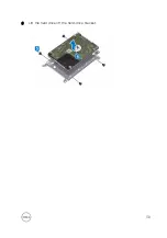
Align the screw holes on the hard-drive bracket with the screw holes on the
hard drive.
2
Replace the four screws (M3x3) that secure the hard-drive bracket to the hard
drive.
3
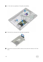
Connect the interposer to the hard drive.
4
Place the hard-drive assembly in the palm-rest assembly and align the screw
holes on the hard-drive assembly with the screw holes on the palm-rest
assembly.
5
Replace the four screws (M2x3) that secure the hard-drive assembly to the
palm-rest assembly.
6
Slide the hard-drive cable into its connector on the system board and close the
latch to secure the cable.
Post-requisites
1
Follow the procedure from step 2 to step 8 in “
2
Replace the
3
Follow the procedure from step 4 to step 5 in “
4
Replace the
40
Summary of Contents for Inspiron 15 3000 Series
Page 24: ...6 Lift the keyboard off the palm rest assembly 24 ...
Page 28: ...6 Remove the two screws M2x5 that secure the base cover to the palm rest assembly 28 ...
Page 30: ...9 Remove the optical drive interposer 30 ...
Page 35: ...35 ...
Page 39: ...6 Lift the hard drive off the hard drive bracket 39 ...
Page 42: ...2 Slide and remove the memory module from the memory module slot 42 ...
Page 46: ...4 Slide and remove the wireless card from the wireless card slot 46 ...
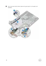
Page 52: ...7 Note the power button board cable routing and peel it off the palm rest assembly 52 ...
Page 54: ...4 Replace the battery 54 ...
Page 59: ...4 Lift the I O board off the palm rest assembly 59 ...
Page 62: ...62 ...
Page 65: ...2 Lift the heat sink off the system board Integrated Eight screws Discrete Four screws 65 ...
Page 68: ...3 Lift the fan off the palm rest assembly 68 ...
Page 71: ...71 ...
Page 77: ...14 Lift the system board off the palm rest assembly 77 ...
Page 81: ...3 Lift the touch pad bracket off the palm rest assembly 81 ...
Page 82: ...4 Lift the touch pad off the palm rest assembly 82 ...
Page 85: ...3 Lift the power adapter port off the palm rest assembly 85 ...
Page 90: ...7 Open the palm rest assembly at an angle and slide it off the display assembly 90 ...
Page 97: ...5 Lift the display panel off the display back cover and antenna assembly 97 ...
Page 100: ...3 Lift the camera off the display back cover and antenna assembly 100 ...
Page 103: ...2 Carefully lift the display hinges off the display back cover and antenna assembly 103 ...
Page 106: ...106 ...
Page 109: ...109 ...


