background image

6. Lift the I/O board along with its cable off the palm-rest and keyboard assembly.

Installing the IO board

Prerequisites

If you are replacing a component, remove the existing component before performing the installation process.

About this task

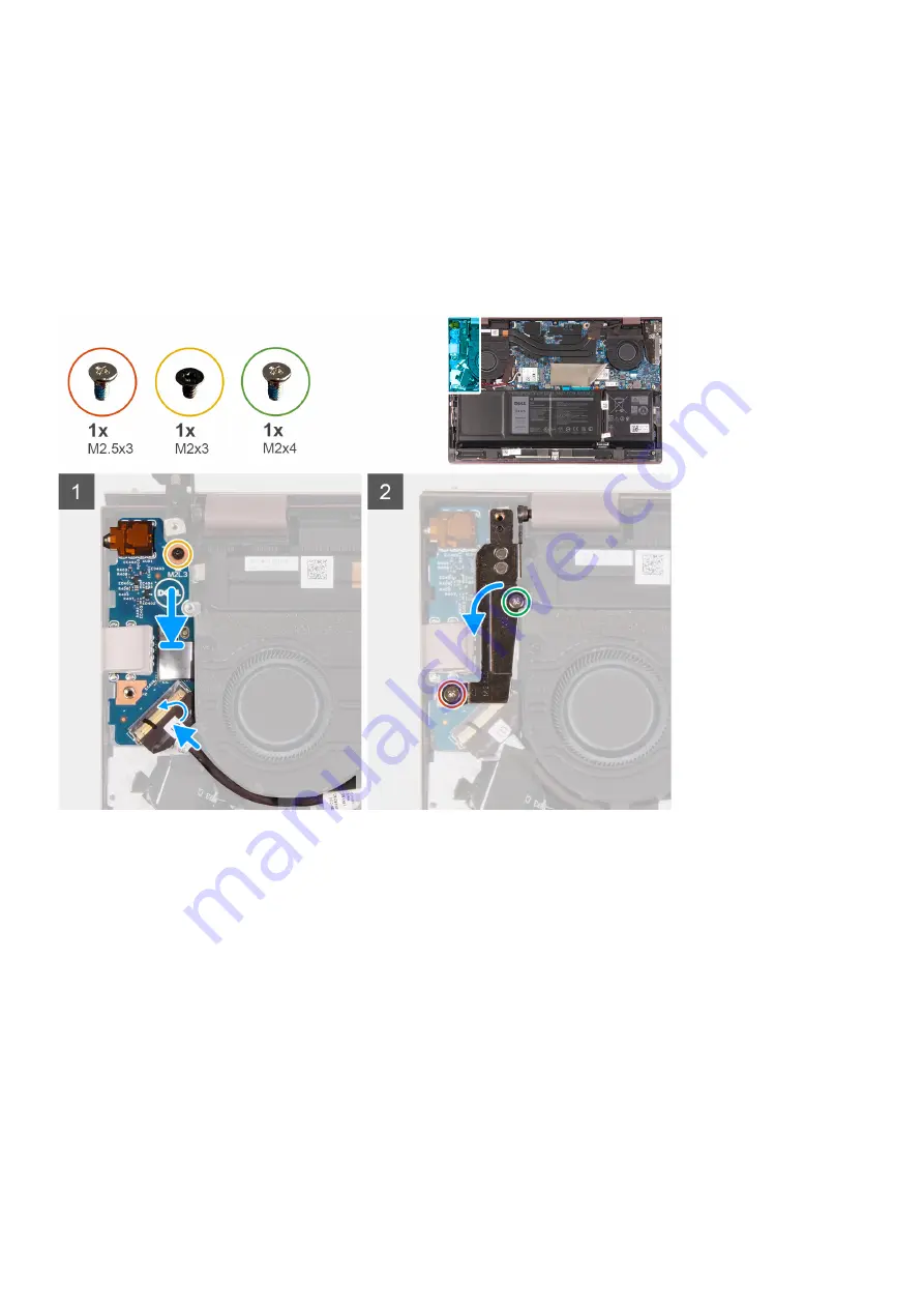
The following image(s) indicate the location of the I/O board and provides a visual representation of the installation procedure.

Steps

1. Align the ports on the I/O board to the slots on the palm-rest and keyboard assembly.
2. Place the I/O board on the palm-rest and keyboard assembly.
3. Align the screw holes on the I/O board to the screw holes on the palm-rest and keyboard assembly.
4. Replace the screw (M2x3) that secures the I/O board to the palm-rest and keyboard assembly.
5. Close the left-display hinge and align the screw holes on the left-display hinge with the screw holes on the palm-rest and

keyboard assembly.

6. Replace the screw (M2x3) that secures the left-display hinge to the palm-rest and keyboard assembly.
7. Replace the screw (M2x4) that secures the left-display hinge to the palm-rest and keyboard assembly.
8. Connect the I/O-board cable to the connector on the I/O board and close the latch.

Next steps

1. Install the 

base cover

.

2. Exit 

Service Mode

.

3. Follow the procedure in 

After working inside your computer

.

Removing and installing components

41

Summary of Contents for Inspiron 13 5310

Page 1: ...Inspiron 13 5310 Service Manual Regulatory Model P145G Regulatory Type P145G001 March 2021 Rev A00 ...

Page 2: ...ential damage to hardware or loss of data and tells you how to avoid the problem WARNING A WARNING indicates a potential for property damage personal injury or death 2021 Dell Inc or its subsidiaries All rights reserved Dell EMC and other trademarks are trademarks of Dell Inc or its subsidiaries Other trademarks may be trademarks of their respective owners ...

Page 3: ... M 2 2230 solid state drive 14 Installing the M 2 2230 solid state drive 16 Removing the M 2 2280 solid state drive 17 Installing the M 2 2280 solid state drive 18 Wireless card 20 Removing the wireless card 20 Installing the wireless card 21 Battery 22 Lithium ion battery precautions 22 Removing the battery 22 Installing the battery 23 Coin cell battery 24 Removing the coin cell battery 24 Instal...

Page 4: ...p 53 Entering BIOS setup program 53 Navigation keys 53 Boot Sequence 54 System setup options 54 Updating the BIOS in Windows 58 Updating BIOS on systems with BitLocker enabled 59 Updating your system BIOS using a USB flash drive 59 Flashing the BIOS from the F12 One Time boot menu 60 System and setup password 63 Assigning a system setup password 63 Deleting or changing an existing system setup pas...

Page 5: ... from the system board To enter Service Mode 1 Shut down your computer and disconnect the AC adapter 2 Hold B key on the keyboard and press the power button for 3 seconds or until the Dell logo appears on the screen 3 Press any key to continue NOTE If the AC adapter has not been disconnected a message prompting you to remove the AC adapter appears on the screen Remove the AC adapter and then press...

Page 6: ...hat may not be obvious such as intermittent problems or a shortened product life span As the industry pushes for lower power requirements and increased density ESD protection is an increasing concern Due to the increased density of semiconductors used in recent Dell products the sensitivity to static damage is now higher than in previous Dell products For this reason some previously approved metho...

Page 7: ...test is successful a red LED is lit and an alarm sounds if the test fails Insulator Elements It is critical to keep ESD sensitive devices such as plastic heat sink casings away from internal parts that are insulators and often highly charged Working Environment Before deploying the ESD Field Service kit assess the situation at the customer location For example deploying the kit for a server enviro...

Page 8: ...he load Avoid twisting your body and back 6 Follow the same techniques in reverse to set the load down Exiting Service Mode Service Mode allows users to immediately cut off electricity from the computer and conduct repairs without disconnecting the battery cable from the system board To exit Service Mode 1 Connect the AC adapter to the power adapter port on your computer 2 Press the power button t...

Page 9: ...the correct number of screws and correct screw type is restored when the component is replaced NOTE Some computers have magnetic surfaces Ensure that the screws are not left attached to such surfaces when replacing a component NOTE Screw color may vary with the configuration ordered Table 1 Screw list Component Screw type Quantity Screw image Base cover M2x4 5 Battery M2x3 5 Solid state drive M2x3...

Page 10: ...antity Screw image I O board M2x3 1 Touchpad M2x2 2 Touchpad bracket M2x2 4 Type C port bracket M2x4 2 Major components of Inspiron 13 5310 The following image shows the major components of Inspiron 13 5310 10 Removing and installing components ...

Page 11: ...lay assembly 8 Coin cell battery 9 Power button with optional fingerprint reader 10 Left speaker 11 System board 12 Heat sink 13 Wireless card bracket 14 Wireless card 15 Left fan 16 M 2 2280 solid state drive if installed 17 M 2 2230 solid state drive if installed Removing and installing components 11 ...

Page 12: ...e options Base cover Removing the base cover Prerequisites 1 Follow the procedure in Before working inside your computer 2 Enter Service Mode About this task NOTE Before removing the base cover ensure that there is no micro SD card installed in the micro SD card slot on your computer The following image s indicate the location of the base cover and provides a visual representation of the removal p...

Page 13: ...o work on the sides to open the base cover 4 Lift and slide the base cover off the palm rest assembly Installing the base cover Prerequisites If you are replacing a component remove the existing component before performing the installation process About this task The following image s indicate the location of the base cover and provides a visual representation of the installation procedure Removin...

Page 14: ... that secure the base cover to the palm rest assembly Next steps 1 Exit Service Mode 2 Follow the procedure in After working inside your computer Solid state drive Removing the M 2 2230 solid state drive Prerequisites 1 Follow the procedure in Before working inside your computer 2 Enter Service Mode 3 Remove the base cover 14 Removing and installing components ...

Page 15: ...e 2230 mounting bracket M 2 2280 solid state drive The following image s indicate the location of the M 2 2230 solid state drive and provides a visual representation of the removal procedure Steps 1 Peel the Mylar that covers the system board 2 Remove the screw M2x3 that secures the M 2 2230 bracket to the system board 3 Slide and lift the M 2 2230 bracket off the system board 4 Slide and lift the...

Page 16: ...guration ordered The supported card configurations on the M 2 card slot are M 2 2230 solid state drive 2230 mounting bracket M 2 2280 solid state drive The following image s indicate the location of the M 2 2230 solid state drive and provides a visual representation of the installation procedure Steps 1 Align the notch on the M 2 2230 solid state drive with the tab on the M 2 card slot on the syst...

Page 17: ...requisites 1 Follow the procedure in Before working inside your computer 2 Enter Service Mode 3 Remove the base cover About this task NOTE This procedure applies only to computers shipped with a M 2 2280 solid state drive installed NOTE The M 2 card installed on your computer will depend on the configuration ordered The supported card configurations on the M 2 card slota are M 2 2230 solid state d...

Page 18: ...tate drive Prerequisites If you are replacing a component remove the existing component before performing the installation process About this task NOTE This procedure applies if you are installing a M 2 2280 solid state drive NOTE The M 2 card installed on your computer will depend on the configuration ordered The supported card configurations on the M 2 card slot are M 2 2230 solid state drive 22...

Page 19: ...he M 2 card slot on the system board 2 Slide the M 2 2280 solid state drive into the M 2 card slot on the system board 3 Replace the screw M2x3 that secures the M 2 2280 solid state drive to the palm rest and keyboard assembly 4 Place the Mylar over the system board Next steps 1 Install the base cover 2 Exit Service Mode 3 Follow the procedure in After working inside your computer Removing and ins...

Page 20: ...s indicate the location of the wireless card and provides a visual representation of the removal procedure Steps 1 Lift the Mylar off the system board 2 Remove the screw M2x3 that secures the wireless card bracket to the palm rest and keyboard assembly 3 Lift the wireless card bracket off the wireless card 4 Disconnect the antenna cables from the wireless card 20 Removing and installing components...

Page 21: ...installation process About this task The following image s indicate the location of the wireless card and provides a visual representation of the installation procedure Steps 1 Align the notch on the wireless card with the tab on the M 2 card slot on the system board 2 Slide the wireless card into the M 2 card slot on the system board Table 2 Antenna cable color scheme Removing and installing comp...

Page 22: ...ate or penetrate the battery with foreign objects Do not expose the battery to high temperatures or disassemble battery packs and cells Do not apply pressure to the surface of the battery Do not bend the battery Do not use tools of any kind to pry on or against the battery Ensure any screws during the servicing of this product are not lost or misplaced to prevent accidental puncture or damage to t...

Page 23: ...e battery cable from the system board if applicable Installing the battery Prerequisites If you are replacing a component remove the existing component before performing the installation process About this task The following image s indicate the location of the battery and provides a visual representation of the installation procedure Removing and installing components 23 ...

Page 24: ...1 Install the base cover 2 Exit Service Mode 3 Follow the procedure in After working inside your computer Coin cell battery Removing the coin cell battery Prerequisites 1 Follow the procedure in Before working inside your computer 2 Enter Service Mode 3 Remove the base cover About this task The following image s indicate the location of the coin cell battery and provides a visual representation of...

Page 25: ...tery from the palm rest and keyboard assembly Installing the coin cell battery Prerequisites If you are replacing a component remove the existing component before performing the installation process About this task The following image s indicate the location of the coin cell battery and provides a visual representation of the installation procedure Removing and installing components 25 ...

Page 26: ...s 1 Install the base cover 2 Exit Service Mode 3 Follow the procedure in After working inside your computer Speakers Removing the speakers Prerequisites 1 Follow the procedure in Before working inside your computer 2 Remove the base cover 3 Remove the battery About this task The following image s indicate the location of the speakers and provides a visual representation of the removal procedure 26...

Page 27: ...st and keyboard assembly 6 Remove the speaker cable from the routing guides on the palm rest and keyboard assembly 7 Lift the speakers along with its cable off the palm rest and keyboard assembly Installing the speakers Prerequisites If you are replacing a component remove the existing component before performing the installation process About this task The following image s indicate the location ...

Page 28: ...ts place the right speaker on the palm rest and keyboard assembly NOTE Ensure that the alignment posts are threaded through the rubber grommets on the speaker 4 Connect the speaker cable to the connector on the system board 5 Adhere the tape that secures the speaker cable to the palm rest and keyboard assembly 6 Place the Mylar over the system board Next steps 1 Install the battery 2 Install the b...

Page 29: ...2 Remove the two screws M2x3 that secure the left fan to the palm rest and keyboard assembly 3 Disconnect the left fan cable from the system board 4 Lift the left fan off the palm rest and keyboard assembly Installing the left fan Prerequisites If you are replacing a component remove the existing component before performing the installation process About this task The following image s indicate th...

Page 30: ...e system board 5 Adhere the Mylar over the system board Next steps 1 Install the base cover 2 Exit Service Mode 3 Follow the procedure in After working inside your computer Removing the right fan Prerequisites 1 Follow the procedure in Before working inside your computer 2 Enter Service Mode 3 Remove the base cover About this task The following image s indicate the location of the right fan and pr...

Page 31: ...ard 4 Lift the right fan off the palm rest and keyboard assembly Installing the right fan Prerequisites If you are replacing a component remove the existing component before performing the installation process About this task The following image s indicate the location of the right fan and provides a visual representation of the installation procedure Removing and installing components 31 ...

Page 32: ... system board 5 Adhere the Mylar over the system board Next steps 1 Install the base cover 2 Exit Service Mode 3 Follow the procedure in After working inside your computer Touchpad Removing the touchpad Prerequisites 1 Follow the procedure in Before working inside your computer 2 Remove the base cover 3 Remove the battery About this task The following image s indicate the location of the touchpad ...

Page 33: ...M2x2 that secure the touchpad to the palm rest and keyboard assembly 5 Lift the touchpad along with its cable off the palm rest and keyboard assembly Installing the touchpad Prerequisites If you are replacing a component remove the existing component before performing the installation process About this task The following image s indicate the location of the touchpad and provides a visual represen...

Page 34: ...nd keyboard assembly 7 Replace the four screws M2x2 that secure the touchpad bracket to the palm rest and keyboard assembly 8 Connect the touchpad cable to the system board and close the latch Next steps 1 Install the battery 2 Install the base cover 3 Follow the procedure in After working inside your computer Display assembly Removing the display assembly Prerequisites 1 Follow the procedure in B...

Page 35: ...Removing and installing components 35 ...

Page 36: ...d 3 Lift the display cable bracket off the system board 4 Peel the tape that secures the display cable connector latch to the system board 5 Lift the latch and disconnect the display cable from the connector on the system board 6 Remove the screw M2x3 that secures the left display hinge to the palm rest and keyboard assembly 36 Removing and installing components ...

Page 37: ...ly from the palm rest and keyboard assembly CAUTION To avoid damaging the display do not slide the palm rest and keyboard assembly over the display assembly 13 After performing the above steps you are left with the display assembly Installing the display assembly Prerequisites If you are replacing a component remove the existing component before performing the installation process About this task ...

Page 38: ...38 Removing and installing components ...

Page 39: ... rest and keyboard assembly 6 Close the right display hinge and align the screw holes on the right display hinge with the screw holes on the system board 7 Place the Type C port bracket on the palm rest and keyboard assembly 8 Align the screw holes on the Type C port bracket to the screw holes on the right display hinge 9 Replace the two screws M2x4 that secure the Type C port bracket to the palm ...

Page 40: ...e the base cover About this task The following image s indicate the location of the I O board and provides a visual representation of the removal procedure Steps 1 Lift the I O board cable connector latch and disconnect the I O board cable from the I O board 2 Remove the screw M2x3 that secures the left display hinge to the palm rest and keyboard assembly 3 Remove the screw M2x4 that secures the l...

Page 41: ... on the I O board to the screw holes on the palm rest and keyboard assembly 4 Replace the screw M2x3 that secures the I O board to the palm rest and keyboard assembly 5 Close the left display hinge and align the screw holes on the left display hinge with the screw holes on the palm rest and keyboard assembly 6 Replace the screw M2x3 that secures the left display hinge to the palm rest and keyboard...

Page 42: ...t the latch and disconnect the power button and optional fingerprint reader cable from the system board NOTE This step is only applicable to computers shipped with the optional fingerprint reader 2 Lift the power button with optional fingerprint reader off the palm rest and keyboard assembly Installing the power button Prerequisites If you are replacing a component remove the existing component be...

Page 43: ...the base cover 4 Exit Service Mode 5 Follow the procedure in After working inside your computer Heat sink Removing the heat sink Prerequisites 1 Follow the procedure in Before working inside your computer 2 Enter Service Mode 3 Remove the base cover About this task NOTE The heat sink may become hot during normal operation Allow sufficient time for the heat sink to cool before you touch it NOTE For...

Page 44: ...red 2 Lift the heat sink from the system board Installing the heat sink Prerequisites If you are replacing a component remove the existing component before performing the installation process About this task NOTE If either the system board or the heat sink is replaced use the thermal grease provided in the kit to ensure that thermal conductivity is achieved The following image s indicate the locat...

Page 45: ...e configuration ordered 2 In sequential order 1 2 3 4 5 6 7 tighten the seven captive screws M2x2 that secure the heat sink to the system board Next steps 1 Install the base cover 2 Exit Service Mode 3 Follow the procedure in After working inside your computer Removing and installing components 45 ...

Page 46: ... the wireless card 6 Remove the left fan 7 Remove the right fan 8 Remove the heat sink NOTE When removing the system board as a pre requisitive step you may remove the system board with the heat sink installed to maintain the thermal bond between the heat sink and the system board About this task The following image s indicate the location of the system board and provides a visual representation o...

Page 47: ...r cable form the system board 10 Disconnect the coin cell battery from the system board 11 Lift the I O board cable connector latch and disconnect the I O board cable from the system board 12 Disconnect the speaker cable from the system board 13 Lift the latch and disconnect the touchpad cable from the system board 14 Lift the latch and disconnect the keyboard cable from the system board 15 Lift t...

Page 48: ...stem board with the screw holes on the palm rest and keyboard assembly 3 Close the right display hinge and align the screw holes on the right display hinge with the screw holes on the system board 4 Place the Type C port bracket on the palm rest and keyboard assembly 48 Removing and installing components ...

Page 49: ...to the connector on the system board and close the latch 18 Connect the keyboard cable to the connector on the system board and close the latch 19 Connect the keyboard backlight cable to the connector on the system board and close the latch Next steps 1 Install the heat sink 2 Install the left fan 3 Install the right fan 4 Install the wireless card 5 Install the M 2 2230 solid state drive or M 2 2...

Page 50: ...d assembly Prerequisites If you are replacing a component remove the existing component before performing the installation process About this task The following image s indicate the location of the palm rest and keyboard assembly and provides a visual representation of the installation procedure 50 Removing and installing components ...

Page 51: ... steps 1 Install the system board 2 Install the power button 3 Install the IO board 4 Install the display assembly 5 Install the touchpad 6 Install the left fan 7 Install the right fan 8 Install the wireless card 9 Install the battery 10 Install the base cover 11 Follow the procedure in After working inside your computer Removing and installing components 51 ...

Page 52: ...rivers and downloads When troubleshooting downloading or installing drivers it is recommended that you read the Dell Knowledge Based article Drivers and Downloads FAQ SLN128938 3 52 Drivers and downloads ...

Page 53: ...ling base devices Entering BIOS setup program Steps 1 Turn on your computer 2 Press F2 immediately to enter the BIOS setup program NOTE If you wait too long and the operating system logo appears continue to wait until you see the desktop Then turn off your computer and try again Navigation keys NOTE For most of the System Setup options changes that you make are recorded but do not take effect unti...

Page 54: ... Overview BIOS Version Displays the BIOS version number Service Tag Displays the Service Tag of the computer Asset Tag Displays the Asset Tag of the computer Manufacture Date Displays the manufacture date of the computer Ownership Date Displays the ownership date of the computer Express Service Code Displays the express service code of the computer Ownership Tag Displays the ownership tag of the c...

Page 55: ...Displays the video memory information of the computer Wi Fi Device Displays the Wi Fi device installed in the computer Native Resolution Displays the native resolution of the computer Video BIOS Version Displays the video BIOS version of the computer Audio Controller Displays the audio controller information of the computer Bluetooth Device Displays whether a Bluetooth device is installed in the c...

Page 56: ... in MM DD YYYY format Changes to the date take effect immediately Time Sets the computer time in HH MM SS 24 hour format You can switch between 12 hour and 24 hour clock Changes to the time take effect immediately Camera Enable Camera Enables or disables the camera By default Enable Camera is selected Audio Enables or disables all integrated audio controller Default ON Enable Microphone Enables or...

Page 57: ...rd Internal HDD 1 Password Enables the user to set change or delete the Internal HDD 1 password Table 10 System setup options Update Recovery menu Update Recovery SupportAssist OS Recovery Enables or disables the boot flow for SupportAssist OS Recovery tool in the event of certain system error Default ON BIOSConnect Enables or disables cloud Service OS recovery if the main OS fails to boot within ...

Page 58: ...vents Default Keep Power Event Log Clear POWER Event Log Select keep or clear Power events Default Keep Updating the BIOS in Windows Prerequisites It is recommended to update your BIOS System Setup when you replace the system board or if an update is available About this task NOTE If BitLocker is enabled it must be suspended before updating the system BIOS and then re enabled after the BIOS update...

Page 59: ...tall For more information on this subject see Knowledge Article https www dell com support article sln153694 Updating your system BIOS using a USB flash drive About this task If the computer cannot load into Windows but there is still a need to update the BIOS download the BIOS file using another computer and save it to a bootable USB flash drive NOTE You must use a bootable USB flash drive For mo...

Page 60: ...n the F12 One Time Boot Menu can use this function Updating from the One Time Boot Menu To update your BIOS from the F12 One Time boot menu you will need USB key formatted to the FAT32 file system key does not have to be bootable BIOS executable file that you downloaded from the Dell Support website and copied to the root of the USB key AC power adapter connected to the system Functional system ba...

Page 61: ...3 The flash BIOS menu will open and then click the Flash from file 4 Select external USB device System setup 61 ...

Page 62: ...5 Once the file is selected Double click the flash target file then press submit 6 Click the Update BIOS then system will reboot to flash the BIOS 62 System setup ...

Page 63: ...vide a basic level of security for the data on your computer CAUTION Anyone can access the data that is stored on your computer if it is not locked and left unattended NOTE System and setup password feature is disabled Assigning a system setup password Prerequisites You can assign a new System or Admin Password only when the status is in Not Set About this task To enter the system setup press F12 ...

Page 64: ...mediately after a power on or reboot Steps 1 In the System BIOS or System Setup screen select System Security and press Enter The System Security screen is displayed 2 In the System Security screen verify that Password Status is Unlocked 3 Select System Password update or delete the existing system password and press Enter or Tab 4 Select Setup Password update or delete the existing setup password...

Page 65: ... To clear the system or BIOS passwords contact Dell technical support as described at www dell com contactdell NOTE For information on how to reset Windows or application passwords refer to the documentation accompanying Windows or your application System setup 65 ...

Page 66: ...hite according to predefined beep codes indicating various failures For example the power and battery status light blinks amber two times followed by a pause and then blinks white three times followed by a pause This 2 3 pattern continues until the computer is turned off indicating no memory or RAM is detected The following table shows different power and battery status light patterns and associat...

Page 67: ...ts simplified messaging SupportAssist On board Diagnostics can be initiated by one of the following methods Pressing F12 to enter one time Boot Menu and selecting Diagnostics to initiate the diagnostics OR Fn Power BIOS POST detecting a hardware failure or error and initiating the diagnostics The SupportAssist On board Diagnostics is embedded with the BIOS and is launched by the BIOS internally Th...

Page 68: ...rticle SLN143196 at www dell com support 3 Copy the BIOS setup program file to the bootable USB drive 4 Connect the bootable USB drive to the computer that needs the BIOS update 5 Restart the computer and press F12 when the Dell logo is displayed on the screen 6 Boot to the USB drive from the One Time Boot Menu 7 Type the BIOS setup program filename and press Enter 8 The BIOS Update Utility appear...

Page 69: ...The following procedure provides the instructions on how to conduct a WiFi power cycle NOTE Some ISPs Internet Service Providers provide a modem router combo device Steps 1 Turn off your computer 2 Turn off the modem 3 Turn off the wireless router 4 Wait for 30 seconds 5 Turn on the wireless router 6 Turn on the modem 7 Turn on your computer Troubleshooting 69 ...

Page 70: ...ick Search to retrieve the related articles Learn and know the following information about your product Product specifications Operating system Setting up and using your product Data backup Troubleshooting and diagnostics Factory and system restore BIOS information See Me and My Dell at www dell com support manuals To locate the Me and My Dell relevant to your product identify your product through...

Reviews: