background image

Steps

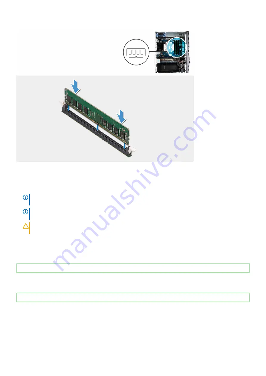
1. Align the notch on the memory module with the tab on the memory-module slot.
2. Insert the memory module into the memory-module connector until the memory module snaps into position and the securing clip locks 

in place.

NOTE: 

The securing clips return to the locked position. If you do not hear the click, remove the memory module and 

reinstall it.

NOTE: 

If the memory module is difficult to remove, gently ease the memory module back and forth to remove it from 

the slot.

CAUTION: 

To prevent damage to the memory module, hold the memory module by the edges. Do not touch the 

components on the memory module.

Next steps

1. Install the 

left-side cover

.

2. Follow the procedure in 

After working inside your computer

.

Identifier

GUID-602E7FD5-CE2D-4838-B813-40F62F9EC1F1

Status

Released

Wireless card

Identifier

GUID-815CFF95-4270-443B-B172-4F8683FD5926

Status

Released

Removing the wireless card

Prerequisites

1. Follow the procedure in 

Before working inside your computer

.

2. Remove the 

left-side cover

.

28

Removing and installing components

Summary of Contents for G5 5090

Page 1: ...G5 5090 Service Manual Regulatory Model D28M Regulatory Type D28M002 ...

Page 2: ...ION indicates either potential damage to hardware or loss of data and tells you how to avoid the problem WARNING A WARNING indicates a potential for property damage personal injury or death 2018 2019 Dell Inc or its subsidiaries All rights reserved Dell EMC and other trademarks are trademarks of Dell Inc or its subsidiaries Other trademarks may be trademarks of their respective owners 2019 08 Rev ...

Page 3: ... 16 Front cover 17 Removing the front cover 17 Installing the front cover 18 2 5 inch hard drive 19 Removing the 2 5 inch hard drive 19 Installing the 2 5 inch hard drive 20 3 5 inch hard drive 21 Removing the 3 5 inch hard drive 22 Installing the 3 5 inch hard drive 23 Chassis fan 24 Removing the chassis fan 24 Installing the chassis fan 25 Memory modules 26 Removing the memory modules 26 Install...

Page 4: ... the system board 51 Installing the system board 55 3 Device drivers 60 Operating system 60 Downloading the audio driver 60 Downloading the graphics driver 60 Downloading the USB driver 61 Downloading the WiFi driver 62 Downloading the chipset driver 62 Downloading the network driver 63 4 System setup 64 System setup 64 BIOS overview 64 Entering BIOS setup program 64 Navigation keys 65 Boot Sequen...

Page 5: ...ssages 81 Recovering the operating system 81 Flashing BIOS USB key 82 Flashing the BIOS 82 WiFi power cycle 82 Flea power release 83 Enabling Intel Optane memory 83 Disabling Intel Optane memory 83 6 Getting help and contacting Dell 85 Contents 5 ...

Page 6: ...g and repairs as authorized or directed by the Dell technical assistance team Damage due to servicing that is not authorized by Dell is not covered by your warranty See the safety instructions that shipped with the product or at www dell com regulatory_compliance CAUTION Before touching anything inside your computer ground yourself by using a wrist grounding strap or by periodically touching an un...

Page 7: ...proximately 80 percent of ESD related failures The high rate of intermittent failures means that most of the time when damage occurs it is not immediately recognizable The DIMM receives a static shock but the tracing is merely weakened and does not immediately produce outward symptoms related to the damage The weakened trace may take weeks or months to melt and in the meantime may cause degradatio...

Page 8: ...s that can cause an ESD event On the work area insulators such as Styrofoam and other plastics should always be moved at least 12 inches or 30 centimeters away from sensitive parts before physically handling any hardware components ESD Packaging All ESD sensitive devices must be shipped and received in static safe packaging Metal static shielded bags are preferred However you should always return ...

Page 9: ...Steps 1 Replace all screws and ensure that no stray screws remain inside your computer 2 Connect any external devices peripherals or cables you removed before working on your computer 3 Replace any media cards discs or any other parts that you removed before working on your computer 4 Connect your computer and all attached devices to their electrical outlets 5 Turn on your computer Working inside ...

Page 10: ...Inside view of your computer NOTE The appearance of heat sink differs depending on the graphics configuration you ordered Figure 1 Inside view of your computer 1 3 5 inch hard drive assembly 2 front cover 3 graphics card 4 power supply unit 5 PCIE door 6 processor fan and heat sink assembly 7 2 5 inch hard drive assembly 8 light bar 2 10 Removing and installing components ...

Page 11: ...TA PWR 4 coin cell battery 5 power supply unit cable connector 6 graphics card slot 7 solid state drive connector m 2 PCIe SSD 8 chassis fan cable connector FAN SYS 9 processor 10 processor power cable connector ATX CPU1 11 processor power cable connector ATX CPU 12 processor fan cable connector FAN CPU 13 memory module slot DIMM3 14 memory module slot DIMM1 15 memory module slot DIMM4 Removing an...

Page 12: ...e correct number of screws and correct screw type is restored when the component is replaced NOTE Some computers have magnetic surfaces Ensure that the screws are not left attached to such surface when replacing a component NOTE Screw color may vary with the configuration ordered Table 1 Screw list Component Secured to Screw type Quantity Screw image Right side cover Chassis 6 32 2 Light bar Chass...

Page 13: ...55 9CE3 4385 BE9A B386DD58CE6A Status Released Removing the left side cover Prerequisites 1 Follow the procedure in Before working inside your computer About this task The following images indicate the location of the left side cover and provides a visual representation of the removal procedure Steps 1 Loosen the two captive screws that secure the left side cover to the chassis Removing and instal...

Page 14: ...he installation procedure About this task The following images indicate the location of the left side cover and provides a visual representation of the installation procedure Steps 1 Align the tabs on the left side cover with the slots on the chassis and slide it towards the front of the computer 2 Tighten the two captive screws that secure the left side cover to the chassis Next steps 1 Follow th...

Page 15: ...ht bar Prerequisites 1 Follow the procedure in Before working inside your computer 2 Remove the left side cover About this task The following images indicate the location of the light bar and provides a visual representation of the removal procedure Steps 1 Disconnect the light bar cable from its connector on the system board Removing and installing components 15 ...

Page 16: ...470F 9054 FFA1CAF0A522 Status Released Installing the light bar Prerequisites If you are replacing a component remove the existing component before performing the installation procedure About this task The following images indicate the location of the light bar and provides a visual representation of the installation procedure Steps 1 Align and slide the tabs on the light bar into the slot on the ...

Page 17: ... Front cover Identifier GUID 8A522B68 98BC 430D BBC0 C06668823D85 Status Released Removing the front cover Prerequisites 1 Follow the procedure in Before working inside your computer 2 Remove the left side cover About this task The following images indicate the location of the front cover and provides a visual representation of the removal procedure Steps 1 Place the computer in an upright positio...

Page 18: ...ore performing the installation procedure About this task The following images indicate the location of the front cover and provides a visual representation of the installation procedure Steps 1 Place the computer in an upright position 2 Connect the front LED cable to the connector on the front cover 3 Align the front cover tabs with the slots on the chassis 4 Rotate the front cover towards the c...

Page 19: ...cedure in Before working inside your computer 2 Remove the left side cover About this task The following images indicate the location of the 2 5 inch hard drive assembly and provides a visual representation of the removal procedure NOTE This computer is not shipped with a 2 5 inch hard drive installed It is shipped with two empty 2 5 inch hard drive cages and a SATA extension cable Removing and in...

Page 20: ... Note the orientation or the SATA connector marking on the hard drive carrier so that you can replace it correctly Identifier GUID 9DB9DF2C 2AAD 4B00 8489 4A0CD817EB71 Status Released Installing the 2 5 inch hard drive Prerequisites If you are replacing a component remove the existing component before performing the installation procedure About this task The following images indicate the location ...

Page 21: ...he slots on the hard drive 2 Slide the hard drive assembly into the hard drive cage until it snaps into place 3 Connect the data cable and power cable to the hard drive Next steps 1 Install the left side cover 2 Follow the procedure in After working inside your computer Identifier GUID DFA3DF29 7400 460D B0A6 B30544A46E4A Status Released 3 5 inch hard drive Removing and installing components 21 ...

Page 22: ...e location of the 3 5 inch hard drive assembly and provides a visual representation of the removal procedure Steps 1 Lay the computer on the right side 2 Remove the screw 6 32 that secures the 3 5 inch hard drive assembly to the chassis 3 Lift the hard drive assembly away from the chassis 4 Remove the cables from the routing guides on the hard drive assembly 5 Disconnect the data and power cables ...

Page 23: ... If you are replacing a component remove the existing component before performing the installation procedure About this task The following images indicate the location of the 3 5 inch hard drive assembly and provides a visual representation of the installation procedure Steps 1 Slide the hard drive into the hard drive cage 2 Replace the four screws 6 32 that secure the hard drive to the hard drive...

Page 24: ...tifier GUID 55DF0237 E5D4 4AE6 855C 4E8A9733E1EC Status Released Chassis fan Identifier GUID 1831E91D 8022 4BAA 9CA1 30B55F1BF67D Status Released Removing the chassis fan Prerequisites 1 Follow the procedure in Before working inside your computer 2 Remove the left side cover 3 Remove the light bar About this task The following images indicate the location of the chassis fan and provides a visual r...

Page 25: ...following images indicate the location of the chassis fan and provides a visual representation of the installation procedure Steps 1 Align the slots on the fan with the rubber grommets on the chassis NOTE The replaceable fan may have tabs inserted in the grommets slots to block the grommets slots and to avoid incorrect installation on the fan Service fan will have tabs plugged on one side to avoid...

Page 26: ...r computer Identifier GUID 2A6DAE1B 1FBE 40F9 8D46 40E8C3FBD267 Status Released Memory modules Identifier GUID 50B70DE0 84DE 4AD1 BA49 C3C8A1F410F1 Status Released Removing the memory modules Prerequisites 1 Follow the procedure in Before working inside your computer 2 Remove the left side cover About this task The following images indicate the location of the memory modules and provides a visual ...

Page 27: ... NOTE If the memory module is difficult to remove gently ease the memory module back and forth to remove it from the slot CAUTION To prevent damage to the memory module hold the memory module by the edges Do not touch the components on the memory module Identifier GUID 0DAE4C68 0D78 4C07 BA7F 41FDE15F2BE4 Status Released Installing the memory modules Prerequisites If you are replacing a component ...

Page 28: ...he memory module back and forth to remove it from the slot CAUTION To prevent damage to the memory module hold the memory module by the edges Do not touch the components on the memory module Next steps 1 Install the left side cover 2 Follow the procedure in After working inside your computer Identifier GUID 602E7FD5 CE2D 4838 B813 40F62F9EC1F1 Status Released Wireless card Identifier GUID 815CFF95...

Page 29: ...to the system board 3 Slide and lift the wireless card bracket off the wireless card 4 Disconnect the antenna cables from the wireless card 5 Slide and remove the wireless card at an angle from the wireless card slot Identifier GUID 01BF7E08 76E2 4C7E 89AC D8336D473992 Status Released Installing the wireless card Prerequisites If you are replacing a component remove the existing component before p...

Page 30: ...olor scheme for the wireless card supported by your computer Table 2 Antenna cable color scheme Connectors on the wireless card Antenna cable color Main white triangle White Auxiliary black triangle Black 2 Slide and place the wireless card bracket on the wireless card 3 Align the notch on the wireless card with the tab on the wireless card slot 4 Slide the wireless card at an angle into the wirel...

Page 31: ...drive Intel Optane Prerequisites NOTE You need to disable the Intel Optane memory before removing Intel Optane from your computer For more information about disabling the Intel Optane memory see Disabling Intel Optane 1 Follow the procedure in Before working inside your computer 2 Remove the left side cover 3 Remove the graphics card About this task The following images indicate the location of th...

Page 32: ...ed Installing the solid state drive Intel Optane Prerequisites CAUTION Solid state drives are fragile Exercise care when handling the solid state drive If you are replacing a component remove the existing component before performing the installation procedure About this task The following images indicate the location of the solid state drive Intel Optane and provides a visual representation of the...

Page 33: ...oard 4 Replace the screw M2x3 that secures the solid state drive Intel Optane to the system board Next steps 1 Install the graphics card 2 Install the left side cover 3 Follow the procedure in After working inside your computer NOTE Enable the Intel Optane memory after you replace the Intel Optane memory module For more information about enabling the Intel Optane memory see Enabling Intel Optane R...

Page 34: ...Removing the graphics card Prerequisites 1 Follow the procedure in Before working inside your computer 2 Remove the left side cover About this task The following images indicate the location of the graphics card and provides a visual representation of the removal procedure Steps 1 Lay the computer on the right side 34 Removing and installing components ...

Page 35: ...oor 6 Push and hold the securing tab on the graphics card slot and lift the graphics card from the graphics card slot NOTE To remove the NVIDIA GeForce RTX 2080 graphics card lift and rotate the graphics card Identifier GUID EA269A94 9752 4E9A BED6 B00D1E7B430C Status Released Installing the graphics card Prerequisites If you are replacing a component remove the existing component before performin...

Page 36: ...eased Coin cell battery Identifier GUID AD775204 4DA1 428A A736 11E8E7C7DD53 Status Released Removing the coin cell battery Prerequisites 1 Follow the procedure in Before working inside your computer NOTE Before working inside your computer read the safety information that shipped with your computer and follow the steps in Before working inside your computer After working inside your computer foll...

Page 37: ...ery Identifier GUID 15487FD4 FEAB 4D7A B067 E7B5DEE0C427 Status Released Installing the coin cell battery Prerequisites If you are replacing a component remove the existing component before performing the installation procedure About this task The following images indicate the location of the coin cell battery and provides a visual representation of the installation procedure Removing and installi...

Page 38: ... 25D8 40F7 BDC2 D98C9BD9C4B6 Status Released Removing the power supply unit Prerequisites 1 Follow the procedure in Before working inside your computer 2 Remove the left side cover 3 Remove the graphics card 4 Remove the 3 5 inch hard drive NOTE Note the routing of all cables as you remove them so that you can route them correctly while you are replacing the power supply unit About this task The f...

Page 39: ...Removing and installing components 39 ...

Page 40: ...ide the power supply unit away from the back of the chassis 7 Lift the power supply unit off the chassis Identifier GUID 38C69312 0C2F 46E0 9FCE B731779CE72D Status Released Installing the power supply unit Prerequisites If you are replacing a component remove the existing component before performing the installation procedure WARNING The cables and ports on the back of the power supply unit are c...

Page 41: ...Removing and installing components 41 ...

Page 42: ...the power supply unit to the chassis 4 Slide and align the screw holes on the power supply unit cover with the screw holes on the chassis NOTE Only the computer with clear doors are shipped with power supply unit cover This step is applicable only for computers shipped with power supply unit cover 5 Replace the two screws 6 32 that secure the power supply unit to the chassis Next steps 1 Install t...

Page 43: ...rking inside your computer NOTE The heat sink may become hot during normal operation Allow sufficient time for the heat sink to cool before you touch it CAUTION For maximum cooling of the processor do not touch the heat transfer areas on the heat sink The oils in your skin can reduce the heat transfer capability of the thermal grease 2 Remove the left side cover About this task The following image...

Page 44: ...ng the installation procedure CAUTION If either the processor or the heat sink is replaced use the thermal grease provided in the kit to ensure that thermal conductivity is achieved About this task The following images indicate the location of the processor fan and heat sink assembly and provides a visual representation of the installation procedure Steps 1 Align the numbering on the processor fan...

Page 45: ...processor Prerequisites 1 Follow the procedure in Before working inside your computer 2 Remove the left side cover 3 Remove the processor fan and heat sink assembly WARNING The processor might still be hot after the computer is shut down Allow the processor to cool down before removing it About this task The following images indicate the location of the processor and provides a visual representati...

Page 46: ... to fall on the pins in the socket 3 Gently lift the processor from the processor socket Identifier GUID 4F27517D D874 45A4 842F 44330252F6AC Status Released Installing the processor Prerequisites If you are replacing a component remove the existing component before performing the installation procedure About this task The following images indicate the location of the processor and provides a visu...

Page 47: ...others the processor is not seated properly 2 Align the notches on the processor with the tabs on the processor socket and place the processor in the processor socket CAUTION Ensure that the processor cover notch is positioned underneath the alignment post 3 When the processor is fully seated in the socket pivot the release lever down and place it under the tab on the processor cover Next steps 1 ...

Page 48: ...ocessor do not touch the heat transfer areas on the heat sink The oils in your skin can reduce the heat transfer capability of the thermal grease NOTE The VR heat sink is shipped as a separate unit and it does not ship along with the system board Ensure to replace the VR heat sink from old system board to the new system board 2 Remove the left side cover About this task The following images indica...

Page 49: ...stallation procedure About this task The following images indicate the location of the VR heat sink and provides a visual representation of the installation procedure Steps 1 Align and place the VR heat sink on the system board 2 Tighten the captive screws that secure the VR heat sink to the system board Next steps 1 Install the left side cover 2 Follow the procedure in After working inside your c...

Page 50: ...provides a visual representation of the removal procedure Steps 1 Disconnect the light bar cable and the front LED cable from their respective connectors on the LED daughter board 2 Remove the screw M2x3 that secures the LED daughter board to the system board 3 Slide and remove the LED daughter board off the system board Identifier GUID C47D51F9 CA07 4CB8 AAC7 BC4786BCA842 Status Released Installi...

Page 51: ...BF Status Released System board Identifier GUID 0D33162E A036 49D7 97CC C79D09691FD5 Status Released Removing the system board Prerequisites 1 Follow the procedure in Before working inside your computer NOTE Your computer s Service Tag is stored in the system board You must enter the Service Tag in the BIOS setup program after you replace the system board NOTE Replacing the system board removes an...

Page 52: ... Remove the coin cell battery 10 Remove the processor fan and heat sink assembly 11 Remove the processor 12 Remove the LED daughter board About this task Figure 3 System board components 1 wireless card slot 2 hard drive data cable connector SATA0 3 hard drive power cable connector SATA PWR 4 coin cell battery 5 power supply unit cable connector 6 graphics card slot 52 Removing and installing comp...

Page 53: ...nector ATX CPU 12 processor fan cable connector FAN CPU 13 memory module slot DIMM3 14 memory module slot DIMM1 15 memory module slot DIMM4 16 memory module slot DIMM2 17 front LED cable connector PWR SW The following images indicate the location of the system board and provides a visual representation of the removal procedure Removing and installing components 53 ...

Page 54: ...ting of all cables as you remove them so that you can route them correctly after you replace the system board For information on system board connectors see System board components 54 Removing and installing components ...

Page 55: ... 32 and that secure the system board to the chassis 6 Remove the VR heat sink NOTE The VR heat sink is shipped as a separate unit and it does not ship along with the system board Ensure that you replace the VR heat sink from old system board to the new system board 7 Remove the screw M2x4 and that secures the system board to the chassis 8 Lift the system board at an angle and remove it off the cha...

Page 56: ... fan cable connector FAN SYS 9 processor 10 processor power cable connector ATX CPU1 11 processor power cable connector ATX CPU 12 processor fan cable connector FAN CPU 13 memory module slot DIMM3 14 memory module slot DIMM1 15 memory module slot DIMM4 16 memory module slot DIMM2 17 front LED cable connector PWR SW The following images indicate the location of the system board and provides a visua...

Page 57: ...Removing and installing components 57 ...

Page 58: ...does not ship along with the system board Ensure that you replace the VR heat sink from old system board to the new system board 4 Replace the eight screws 6 32 that secure the system board to the chassis 5 Route and connect all the cables that you disconnected from the system board NOTE For information on system board connectors see System board components 6 Align the front I O bracket with the s...

Page 59: ...cover 10 Install the light bar 11 Install the left side cover 12 Follow the procedure in After working inside your computer NOTE Your computer s Service Tag is stored in the system board You must enter the Service Tag in the BIOS setup program after you replace the system board NOTE Replacing the system board removes any changes you have made to the BIOS using the BIOS setup program You must make ...

Page 60: ...uctions for browser specific instructions 8 Click View Drivers for My System 9 Click Download and Install to download and install all driver updates detected for your computer 10 Select a location to save the files 11 If prompted approve requests from User Account Control to make changes on the system 12 The application installs all drivers and updates identified NOTE Not all files can be installe...

Page 61: ...on the screen to install the driver Identifier GUID 8FFA775C 7C2B 4BAD 90F5 2EAEAB4F47B3 Status Released Downloading the USB driver Steps 1 Turn on your computer 2 Go to www dell com support 3 Enter the Service Tag of your computer and then click Submit NOTE If you do not have the Service Tag use the auto detect feature or manually browse for your computer model 4 Click Drivers downloads 5 Click t...

Page 62: ...d and installation click Category 14 Click Network in the drop down list 15 Click Download to download the WiFi driver for your computer 16 After the download is complete navigate to the folder where you saved the WiFi driver file 17 Double click the WiFi driver icon and follow the instructions on the screen to install the driver Identifier GUID 68AD9874 365F 41C0 B35F D6E140B893DC Status Released...

Page 63: ... Drivers button 6 Review and agree to the Terms and Conditions to use SupportAssist then click Continue 7 If necessary your computer starts to download and install SupportAssist NOTE Review on screen instructions for browser specific instructions 8 Click View Drivers for My System 9 Click Download and Install to download and install all driver updates detected for your computer 10 Select a locatio...

Page 64: ...ou write down the BIOS Setup program screen information for future reference Use the BIOS Setup program for the following purposes Get information about the hardware installed in your computer such as the amount of RAM and the size of the hard drive Change the system configuration information Set or change a user selectable option such as the user password type of hard drive installed and enabling...

Page 65: ...en the Dell logo appears you can Access System Setup by pressing F2 key Bring up the one time boot menu by pressing F12 key The one time boot menu displays the devices that you can boot from including the diagnostic option The boot menu options are Removable Drive if available STXXXX Drive if available NOTE XXX denotes the SATA drive number Optical Drive if available SATA Hard Drive if available D...

Page 66: ...mation Processor Type Displays the processor type Core Count Displays the number of cores on the processor Processor ID Displays the processor identification code Current Clock Speed Displays the current processor clock speed Minimum Clock Speed Displays the minimum processor clock speed Maximum Clock Speed Displays the maximum processor clock speed Processor L2 Cache Displays the Processor L2 Cac...

Page 67: ...SS AM PM format Table 4 System setup options System Configuration menu System Configuration Integrated NIC Controls the on board LAN controller Enable UEFI Network Stack Enable or disable UEFI Network Stack Front bezel LED Light Intensity Control Enable disable or adjust the Front bezel LED Light Intensity to Low or medium Serial port Enable or disable the serial ports SATA Operation Configure ope...

Page 68: ... delete the system password Internal HDD 0 Password Set change or delete the internal hard disk drive password Internal HDD 1 Password Set change or delete the internal hard disk drive password Internal HDD 2 Password Set change or delete the internal hard disk drive password Internal HDD 3 Password Set change or delete the internal hard disk drive password M 2 SATA SSD Password Set change or dele...

Page 69: ...es Deployed Mode Default Enabled Audit Mode Default Disabled Deployed Mode Enable or disable the deployed mode Audit Mode Enable or disable the audit mode Expert Key Management Expert Key Management Enable or disable Expert Key Management Custom Mode Key Management Select the custom values for expert key management Table 8 System setup options Intel Software Guard Extensions menu Intel Software Gu...

Page 70: ...boot process Default Thorough Extend BIOS POST Time Configure additional pre boot delay Full Screen Logo Enable or disable to display full screen logo Warnings and Errors Sets the boot process to pause when Warnings or Errors are detected Table 9 System setup options Virtualization Support menu Virtualization Support Virtualization Specify whether a Virtual Machine Monitor VMM can utilize the addi...

Page 71: ...e password features provide a basic level of security for the data on your computer CAUTION Anyone can access the data stored on your computer if it is not locked and left unattended NOTE System and setup password feature is disabled Identifier GUID D91DBF33 F0AB 477E A22D D6CD2D066BBE Status Released Assigning a system setup password Prerequisites You can assign a new System or Admin Password onl...

Page 72: ...word Status is Unlocked 3 Select System Password alter or delete the existing system password and press Enter or Tab 4 Select Setup Password alter or delete the existing setup password and press Enter or Tab NOTE If you change the System and or Setup password re enter the new password when prompted If you delete the System and or Setup password confirm the deletion when prompted 5 Press Esc and a ...

Page 73: ...System Setup and System passwords About this task CAUTION Clearing CMOS settings will reset the BIOS settings on your computer Steps 1 Remove the left side cover 2 Remove the graphics card 3 Remove the jumper plug from the password jumper pins PSWD 4 Wait for 5 seconds and then replace the jumper plug to its original location System setup 73 ...

Page 74: ...5 Install the graphics card 6 Install the left side cover 74 System setup ...

Page 75: ...messages that inform you of problems encountered during testing NOTE Some tests for specific devices require user interaction Always ensure that you are present at the computer terminal when the diagnostic tests are performed For more information see Dell EPSA Diagnostic 3 0 Identifier GUID 0B893EED EFBC 4831 A9C4 7298A7A9F619 Status Released Running the ePSA diagnostics Steps 1 Turn on your compu...

Page 76: ...RGD_PS This entry provides for the possibility of a delay from SLP_S3 active to PWRGD_PS inactive Blinking Off S0 no PWRGD_PS Boot Failure The computer is receiving electrical power and power supplied by the power supply is normal A device might be malfunctioning or incorrectly installed Refer to the table below for Amber Blinking Pattern diagnostics suggestion and possible failures Steady Off S0 ...

Page 77: ...BIOS Post code Old LED pattern 1001 Fatal Motherboard error 3 5 BIOS state 8 BIOS Post code Old LED pattern 1010 Mem config modules incompatible or invalid config 3 6 BIOS state 9 BIOS Post code Old LED pattern 1011 combine Other pre video activity and resource configuration codes BIOS to eliminate 1100 code 3 7 BIOS state 10 BIOS Post code Old LED pattern 1110 Other pre post activity routine subs...

Page 78: ...e internal to the microprocessor has failed Contact Dell CD DRIVE CONTROLLER FAILURE The optical drive does not respond to commands from the computer DATA ERROR The hard drive cannot read the data DECREASING AVAILABLE MEMORY One or more memory modules may be faulty or improperly seated Reinstall the memory modules or if necessary replace them DISK C FAILED INITIALIZATION The hard drive failed init...

Page 79: ...rom an optical Then shut down the computer reinstall the hard drive and restart the computer If the problem persists try another drive Run the Hard Disk Drive tests in Dell Diagnostics INSERT BOOTABLE MEDIA The operating system is trying to boot to non bootable media such as an optical drive Insert bootable media INVALID CONFIGURATION INFORMATION PLEASE RUN SYSTEM SETUP PROGRAM The system configur...

Page 80: ... Dell SECTOR NOT FOUND The operating system cannot locate a sector on the hard drive You may have a defective sector or corrupted File Allocation Table FAT on the hard drive Run the Windows error checking utility to check the file structure on the hard drive See Windows Help and Support for instructions click Start Help and Support If a large number of sectors are defective back up the data if pos...

Page 81: ...nce information is correct No timer tick interrupt A chip on the system board might be malfunctioning or motherboard failure NOTICE Hard Drive SELF MONITORING SYSTEM has reported that a parameter has exceeded its normal operating range Dell recommends that you back up your data regularly A parameter out of range may or may not indicate a potential hard drive problem S M A R T error possible hard d...

Page 82: ...o flash the BIOS Steps 1 Turn on your computer 2 Go to www dell com support 3 Click Product support enter the Service Tag of your computer and then click Submit NOTE If you do not have the Service Tag use the auto detect feature or manually browse for your computer model 4 Click Drivers downloads Find it myself 5 Select the operating system installed on your computer 6 Scroll down the page and exp...

Page 83: ...able to enable the Intel Optane memory 4 On the warning screen select a compatible fast drive and then click Yes to continue enabling Intel Optane memory 5 Click Intel Optane memory Reboot to complete enabling your Intel Optane memory NOTE Applications may take up to three subsequent launches after enablement to see the full performance benefits Identifier GUID CD2E8B90 160E 43C9 BA9D F0F6C6BAA458...

Page 84: ... storage do not disable the Intel Optane memory The Disable option will be grayed out 4 Click Yes if you accept the warning The disabling progress is displayed 5 Click Reboot to complete disabling your Intel Optane memory and restart your computer 84 Troubleshooting ...

Page 85: ...arch box 3 Click Search to retrieve the related articles Learn and know the following information about your product Product specifications Operating system Setting up and using your product Data backup Troubleshooting and diagnostics Factory and system restore BIOS information See Me and My Dell at www dell com support manuals To locate the Me and My Dell relevant to your product identify your pr...

Reviews: