22
|
Install the S55
www.dell.com | support.dell.com
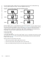
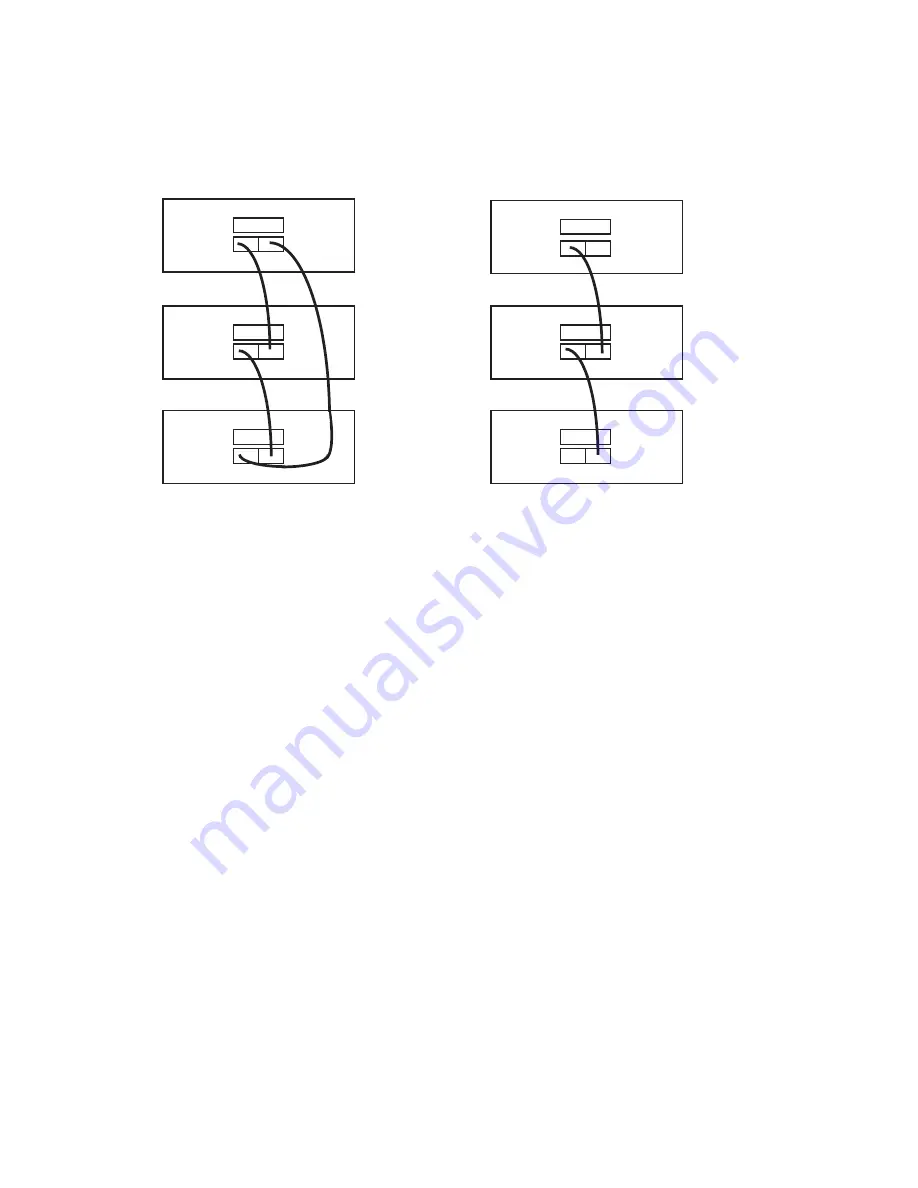
The S55 supports stacking in either a ring or cascade topology. Dell Force10 recommends the ring
topology when stacking S55 switches, to provide redundant connectivity.
Figure 4-1. S55 stacking topology with 2-port 12G stacking module
While the diagram shows A-to-B connections, the ports are bi-directional, so you can connect A-to-A or
B-to-B, as shown below in examples of two-switch (
or insert them into a cabinet before you make your stacking port connections. Insert one end of the
stacking cable into a stacking port, and insert the other end into a stacking port of the adjacent switch.
Hand-tighten all captive screws to ensure that the cable is secure in the connector.
Connect two S55s
2-port 12G stacking modules
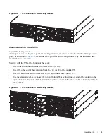
As an option, when using the 2-port 12G stacking modules, insert a second cable into the other open stack
ports, as shown in
. The second cable provides both backup connectivity and increased data
transfer between the units.
Starting with the S55 at the bottom of the stack:
•
Insert one end of the first cable into Stack Port 48 (or 49).
•
Insert the other end of the cable into Stack Port 48 (or 49) of the top.
•
Insert a second cable into Stack Port 49 (or 48) of the bottom and top S55s.
Switch 1
Switch 2
Switch 3
Switch 1
Switch 2
Switch 3
48
49
48
49
48
49
48
49
48
49
48
49
Summary of Contents for Force10 S55
Page 1: ...Installing the S55 System ...
Page 12: ...12 The S55 System w w w d e l l c o m s u p p o r t d e l l c o m ...
Page 16: ...16 Site Preparations w w w d e l l c o m s u p p o r t d e l l c o m ...
Page 30: ...30 Power Supplies w w w d e l l c o m s u p p o r t d e l l c o m ...
Page 36: ...36 Access the console ports w w w d e l l c o m s u p p o r t d e l l c o m ...
Page 48: ...48 Technical Support w w w d e l l c o m s u p p o r t d e l l c o m ...
Page 49: ......
Page 50: ...w w w d ell com support dell com Printed in the U S A ...

