18
|
Installing the Switch
www.dell.com | support.dell.com
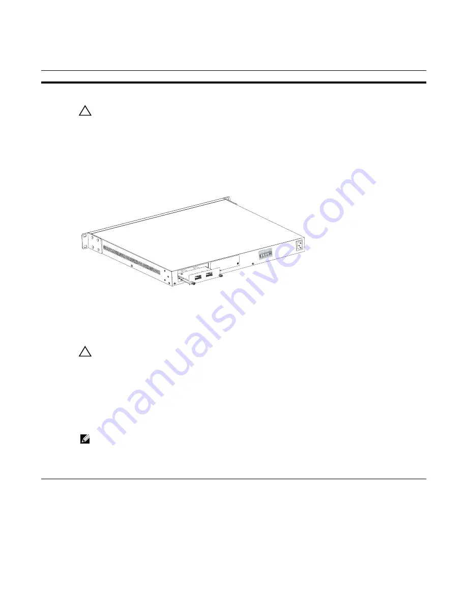
To install a module, follow the steps below:
Installing the System on a Tabletop
The system can be positioned on a stable tabletop. Four rubber standoffs are provided for that purpose in
the plastic bag in the switch shipping box. Keep the following in mind when using a tabletop:
Step
Task
1
If the system is on, save the running configuration, if desired (and different from the startup configuration) with
the command write memory. Then power down the system by unplugging it from its power source.
CAUTION:
Hot-swapping (inserting or removing) a module can crash and lock up the system, requiring a
power cycle.
2
Use a #2 Phillips screwdriver to remove either a module faceplate or an existing module. Note that these slots,
when used for 10G Ethernet ports, are assigned port numbers from left to right as you face the front of the system.
So, for clarity in programming those ports, you might favor the left-most slot for the first 10G module that you
install.
3
Grasp the module faceplate, and remove the module from its packaging, then slide it into the slot until the module
faceplate is flush with the rear cover of the system.
4
Secure the captive screws on either side of the module.
5
The optical XFP 10-Gigabit module (Catalog # S50-01-10GE-2P) requires additional XFP transceiver inserts,
which are not included in the module kit. See
the installation instructions that come
with the transceiver.
CAUTION:
You can connect a CX4 cable to an XFP port through a CX4 XFP converter (catalog number
GP- XFP-1CX4) in the slot. However, an XFP port does not support the use of the cx4-cable-length command,
discussed next.
CX4 module (catalog number S50-01-10GE-2C) ports do not require inserts. If you are installing a CX4 module,
and you are connecting the ports with a cable substantially shorter or longer than 5 meters, use the cx4-cable-
length command to set the signal strength. Use cx4-cable-length long for a longer cable, cx4-cable-length short
for a shorter cable. For details when using FTOS, see the Interfaces chapter in the
FTOS Command Reference
.
When using SFTOS, see the System Management Commands chapter in the
SFTOS Command Reference
for
details.
NOTE:
Take care not to connect CX4 ports to 12G stack ports in the switch. The receptacles and cables are
the same, but they are incompatible. CX4 ports are labeled as such; stack ports are not labeled. You can order
several cable lengths of each type; they are not part of the module kit. For details, see
Using CX4 Cables
(CX4
Cable Matrix) in the S-Series tech tips on iSupport:
http://www.force10networks.com/CSPortal20/KnowledgeBase/
ToolTipsSSeries.aspx
fn00144s50V
Summary of Contents for Force10 S50N Series
Page 1: ...Installing S50N and S50V Systems ...
Page 8: ...8 About this Guide w w w d e l l c o m s u p p o r t d e l l c o m ...
Page 40: ...40 Installing Backup Power w w w d e l l c o m s u p p o r t d e l l c o m ...
Page 46: ...46 Installing Ports w w w d e l l c o m s u p p o r t d e l l c o m ...
Page 58: ...58 Technical Support w w w d e l l c o m s u p p o r t d e l l c o m ...
Page 63: ......
Page 64: ...w w w d ell com support dell com Printed in the U S A ...


