background image

Installation and Setup

Installing a PS6500 Array

2–24

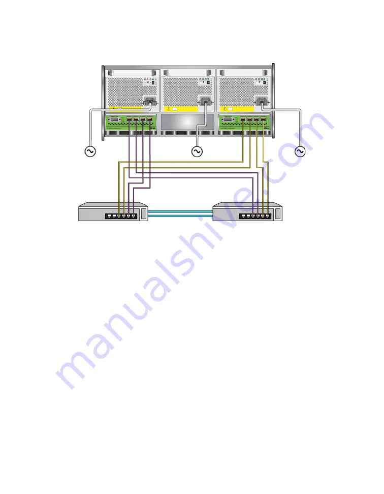
Figure 2-18: Recommended Network Configuration - PS6500

Use the cable management system to organize the network cables, along with the 

power cables. See Figure 2-12 through Figure 2-16.

Step 3: Turn on Power to the Array

Before turning on power, allow sufficient time for the PS6500 to adjust to ambient 

temperature (for example, overnight). 

Turning on the power transitions the array from standby mode to full-power 

mode.

The power switch is on the front of the array. To turn on power to the array you 

must remove the front bezel, as follows:

1. Insert the bezel key and turn it clockwise to unlock the bezel. See Figure 2-19.

Summary of Contents for EqualLogic PS Series

Page 1: ......

Page 2: ...mark All trademarks and registered trademarks mentioned herein are the property of their respective owners Information in this document is subject to change without notice Reproduction in any manner whatsoever without the written permission of Dell is strictly forbidden December 2008 Part Number P631M Rev A01 ...

Page 3: ...ep 2 Connect the Array to the Network 2 9 Step 3 Turn on Power to the Array 2 11 Step 4 Set Up a Serial Connection to the Array 2 11 Installing a PS6500 Array 2 14 Before You Begin 2 14 Environmental Requirements 2 15 Shipping Box Contents and Required Hardware 2 16 Rack Mount Requirements 2 17 Installing the Hardware 2 17 Step 1 Connect the Array to Power 2 18 Step 2 Connect the Array to the Netw...

Page 4: ... Step 4 Set the Member RAID Policy 3 8 Using the CLI to Set the RAID Policy 3 8 Using the GUI to Set the RAID Policy 3 9 4 Storage Allocation 4 1 Step 1 Create a Volume 4 1 Using the CLI to Create a Volume 4 2 Using the GUI to Create a Volume 4 3 Step 2 Connect a Computer to a Volume 4 5 5 Where to Go Next 5 1 Common Group Customization Tasks 5 1 Advanced Group Administration Tasks 5 2 Index Index...

Page 5: ... may be useful to understand Basic networking concepts Current network environment User disk storage requirements RAID configurations Disk storage management Note Although this manual provides examples of using PS Series arrays in some common network configurations detailed information about setting up a network is beyond its scope Organization This manual is organized as follows Chapter 1 Steps f...

Page 6: ...ries Group Administration Describes how to use the Group Manager graphical user interface GUI to manage a PS Series group This manual provides comprehensive information about product concepts and procedures PS Series CLI Reference Describes how to use the Group Manager command line interface CLI to manage a PS Series group and individual arrays PS Series Online help In the Group Manager GUI expand...

Page 7: ...945 3355 Note If you do not have an Internet connection you can find contact information on your purchase invoice packing slip bill or Dell product catalog To contact Dell for sales technical support or customer service issues 1 Visit support dell com 2 Verify your country or region in the Choose A Country Region drop down menu at the bottom of the window 3 Click Contact Us on the left side of the...

Page 8: ... www dell com la Latin American countries www dell ca Canada only You can access Dell Support through the following websites support dell com support dell com EqualLogic support jp dell com Japan only support euro dell com Europe only ...

Page 9: ...oup capacity and performance increase automatically There are two methods for configuring the software If you have a Windows computer and meet the requirements use the Remote Setup Wizard The setup utility is supported in all environments See Chapter 3 Software Configuration 3 Start using the SAN Allocate group storage space to users and applications by creating volumes A volume appears on the net...

Page 10: ......

Page 11: ...the software as described in Chapter 3 Software Configuration Protecting Hardware Protect a PS Series array from electrostatic discharge When handling array hardware make sure you use the electrostatic wrist strap that is shipped with the array or a similar form of protection To use the wrist strap 1 Connect the steel snap on the coil cord to the stud on the elastic band See Figure 2 1 Figure 2 1 ...

Page 12: ... or 100 Mbits performance will be slower than when using a Gigabit Ethernet switch Multiple network connections to different network switches For increased bandwidth and availability connect all the network interfaces on both control modules to multiple network switches The switches must be connected using interswitch links The links must have sufficient bandwidth to handle the iSCSI traffic After...

Page 13: ... You can use Spanning Tree for a single cable connection between switches and you can use trunking for multi cable connections between switches Flow Control enabled on switches and NICs Enable Flow Control on each switch port and NIC that handles iSCSI traffic PS Series arrays will correctly respond to Flow Control Unicast storm control disabled on switches Disable unicast storm control on each sw...

Page 14: ...Figure 2 2 PS6000 Array Front View Figure 2 3 PS6000 Array Rear View Before You Begin You must meet these prerequisites before installing a PS6000 array Make sure the array and installation location meet the environmental requirements See Environmental Requirements on page 2 5 Gather all the required hardware See Shipping Box Contents and Required Hardware on page 2 6 Rack mount the array See Rack...

Page 15: ...0 Technical Specifications Component Requirement Weight of fully loaded array 77 6 pounds or 35 kilograms Operating temperature 41 to 95 degrees F 5 to 35 degrees C Storage temperature 22 to 140 degrees F 30 to 60 degrees C Operating altitude 10 000 feet 3048 meters Operational relative humidity 20 to 80 percent non condensing Thermal output fully loaded array 1700 BTU hour SAS disks 1550 BTU hour...

Page 16: ...e shipping box may contain different types of power cables to meet the electrical requirements of the country in which the array will reside Use the cable type that is right for your environment If power cables are not included in the shipping box contact your PS Series array support provider or reseller Serial cable Creates a serial connection between an array and a console or terminal emulator U...

Page 17: ... in the array shipping box includes installation and mounting instructions Installing the Hardware Make sure you complete the preliminary tasks described in Before You Begin on page 2 4 Then follow these steps to install a PS6000 array 1 Connect the power cables Do not turn on power to the array at this time See Step 1 Connect the Array to Power on page 2 8 Table 2 4 Required Hardware Not Supplied...

Page 18: ...ioning power supply and cooling module connected to a source of power is required for array operation Obtain the power cables that were shipped with the array If the array was not shipped with power cables see your PS Series support provider or reseller for power cable information Connect both power supply and cooling modules to a source of power Use the cable strain relief to secure each power ca...

Page 19: ...to 3 One functioning network connection is required for array operation Multiple network connections are recommended for performance and high availability See Table 2 1 for additional network recommendations Obtain two to eight network cables Network cables are not included in the array shipping box See Table 2 4 for supported network cable types At a minimum connect network cables to Ethernet 0 o...

Page 20: ...imum network bandwidth and availability it is recommended that you use eight network cables to connect all the network interfaces to multiple network switches The switches must be connected with interswitch links that have sufficient bandwidth See Figure 2 6 Figure 2 6 Recommended Network Configuration PS6000 ...

Page 21: ...you must set up a serial connection If you plan to use the Remote Setup Wizard you do not need a serial connection See Step 1 Choose a Configuration Method on page 3 1 for information about Remote Setup Wizard requirements Note The serial cable that was shipped with the array is a standard null modem cable with a female DB9 connector Figure 2 7 on each end You might have to make or buy an adapter ...

Page 22: ...al or a computer running a terminal emulator See Figure 2 8 not to scale Figure 2 8 Connecting a Serial Cable to the Array System Ground 5 5 System Ground Data Set Ready Carrier Detect 6 1 4 Data Terminal Ready Request to Send 7 8 Clear to Send Clear to Send 8 7 Request to Send Table 2 5 DB9 to DB9 Pinout Information Continued DB9 1 DB9 2 Function Pin Pin Function ...

Page 23: ...ollowing characteristics 9600 baud One STOP bit No parity 8 data bits No flow control Note Keep the serial cable You must use the serial cable to manage the group or a specific array if there is no network access After completing the hardware installation see Chapter 3 Software Configuration ...

Page 24: ...Figure 2 9 PS6500 Array Front View Figure 2 10 PS6500 Array Rear View Before You Begin You must meet these prerequisites before installing a PS6500 array Make sure the array and installation location meet the environmental requirements See Environmental Requirements on page 2 15 Gather all the required hardware See Shipping Box Contents and Required Hardware on page 2 16 Rack mount the array See R...

Page 25: ...nted Review the technical specifications inTable 2 6 to make sure your environment supports its requirements Table 2 6 PS6500 Technical Specifications Component Requirement Weight without disk drives 77 pounds 35kg Weight with disk drives 177 pounds 80kg Operating temperature 41 to 95 degrees F 5 to 35 degrees C Storage temperature 34 to 140 degrees F 1 to 60 degrees C Operating altitude 0 to 10 0...

Page 26: ...ckaging until you are ready to install them Power cables The shipping box may contain multiple power cables to meet the electrical requirements of the country in which the array will reside Use the cable that is right for your configuration If power cables are not included in the shipping box contact your PS Series support provider or reseller Serial cable Creates a serial connection between an ar...

Page 27: ... Then follow these steps to install a PS6500 array 1 Connect the power cables Do not turn on power to the array at this time See Step 1 Connect the Array to Power on page 2 18 Documentation The following documentation is included in the shipping box Unpacking Instructions Rack Mount Instructions Setup poster Installation and Setup manual this document License regulatory and warranty information Ta...

Page 28: ...are required for array operation Note See Environmental Requirements on page 2 15 for information about voltage requirements Obtain the power cables that were shipped with the array If the array was not shipped with power cables contact your PS Series support provider or reseller for power cable information Note Dell recommends that you connect the supplied 6 foot 2 m C113 C14 power cables to the ...

Page 29: ...t use the cable management system to organize your power and network cables The cable management system also enables you to open the chassis cover without dislodging the cables The cable management system consists of two wire assemblies as shown in Figure 2 12 One wire assembly has three arms three clamps and six fabric hook and loop fasteners The other wire assembly has one arm two clamps and thr...

Page 30: ...ray chassis and to the rack rails See Figure 2 13 Figure 2 13 Cable Management System Installed See the Rack Mount Instructions for information about installing the cable management system To use the cable management system 1 Gather the power cables and route the cables along the top arm of the three arm assembly going from to as shown in Figure 2 14 Make sure the ...

Page 31: ...three fasteners on the arm and place the cables below the arms See Figure 2 15 Figure 2 15 Attaching the Hook and Loop Fasteners 3 Route the cables along the middle arm of the three arm assembly going from to in Figure 2 14 4 Route the cables along the one arm assembly connected to the top of the left and right rails going from to in Figure 2 14 After routing the cables the installation should res...

Page 32: ...ith power and the array is not operational Step 2 Connect the Array to the Network The PS6500 array includes two control modules Each control module has four network interface ports labeled Ethernet 0 Ethernet 1 Ethernet 2 and Ethernet 3 One functioning network connection is required for array operation Multiple network connections are recommended for performance and high availability See Table 2 ...

Page 33: ...k Configuration PS6500 For maximum bandwidth and availability it is recommended that you use eight network cables to connect all the network interfaces to multiple network switches The switches must be connected with interswitch links that have sufficient bandwidth See Figure 2 18 ...

Page 34: ...16 Step 3 Turn on Power to the Array Before turning on power allow sufficient time for the PS6500 to adjust to ambient temperature for example overnight Turning on the power transitions the array from standby mode to full power mode The power switch is on the front of the array To turn on power to the array you must remove the front bezel as follows 1 Insert the bezel key and turn it clockwise to ...

Page 35: ...t side and push the bezel release latch up on the left side to disengage the bezel from the chassis See Figure 2 20 Figure 2 20 Pushing Up the Bezel Release Latch 3 Pull the bezel away from the chassis See Figure 2 21 Figure 2 21 Detaching the Bezel from the Chassis 4 Press the blue power button on the front panel ...

Page 36: ...use the setup utility to configure the software you must set up a serial connection If you plan to use the Remote Setup Wizard you do not need a serial connection See Step 1 Choose a Configuration Method on page 3 1 for information about Remote Setup Wizard requirements Note The serial cable that was shipped with the array is a standard null modem cable with a female DB9 connector on each end You ...

Page 37: ...nnection must have the following characteristics 9600 baud One STOP bit No parity 8 data bits No flow control Note Keep the serial cable You must use the serial cable to manage the group or an individual array if there is no network access After completing the hardware installation see Chapter 3 Software Configuration ...

Page 38: ......

Page 39: ...e storage and start using the SAN See Chapter 4 Storage Allocation Step 1 Choose a Configuration Method There are two methods for configuring the software Choose one method Use the Remote Setup Wizard Use the setup utility About the Remote Setup Wizard The Remote Setup Wizard is located on the Host Integration Tools CD ROM included in the shipping box and must be installed on a Windows computer If...

Page 40: ...ration To use the setup utility you must have a serial connection between the array and a console terminal or a computer running a terminal emulator After choosing a method collect the information needed for the array configuration Step 2 Collect Configuration Information Regardless of the method you use to configure the software you must collect the information in Table 3 1 and Table 3 2 Obtain I...

Page 41: ...s on the number of drives in the array RAID 10 Striping on top of multiple RAID 1 mirrored sets RAID 50 Striping on top of multiple RAID 5 distributed parity sets Each RAID 5 set has one parity drive RAID 5 Multiple distributed parity sets RAID 6 Multiple dual distributed parity sets Table 3 2 Group Configuration Prompt Description Group name Unique name that identifies the group 63 or fewer lette...

Page 42: ...ormation on how to proceed 2 At the login prompt enter grpadmin for both the account login name and the password Passwords do not appear on the screen 3 When prompted enter y to start the setup utility 4 When prompted enter the array and group configuration information from Table 3 1 and Table 3 2 Press the key to accept a default value Enter a question mark to obtain help Microsoft service user n...

Page 43: ...oup Note There may be a short delay after entering the group IP address as the array searches the network An example of using the setup utility to initialize an array and create a group is shown in Example 3 1 After setup completes you must set the member s RAID policy in order to use the disk storage Go to Step 4 Set the Member RAID Policy on page 3 8 ...

Page 44: ... gateway 192 17 2 1 Enter the name and IP address of the group that the array will join Group name group1 Group IP address 192 17 2 20 Searching to see if the group exists This may take a few minutes The group does not exist or currently cannot be reached Make sure you have entered the correct group IP address and group name Do you want to create a new group yes no yes yes Group Configuration Grou...

Page 45: ...by clicking Start Programs EqualLogic Remote Setup Wizard 5 In the Welcome dialog box select Initialize a PS Series array and click Next Note If you cannot contact the array check the network configuration You may need to use the setup utility to configure the software 6 Select the array that you want to initialize and click Next 7 In the Initialize Array dialog box enter the array configuration f...

Page 46: ... an existing group with the Remote Setup Wizard you must set the RAID policy for the group member Use either the Group Manager command line interface CLI or the graphical user interface GUI to set the RAID policy Using the CLI to Set the RAID Policy To use the Group Manager CLI to set the RAID policy for a new group member 1 Log in to the group if you are not already logged in After the setup util...

Page 47: ... Release Notes To use the GUI to set the RAID policy for a member 1 Log in to the group by entering the group IP address in a Web browser Then in the login dialog box Figure 3 1 enter the grpadmin account name and the password that you specified when creating the group Figure 3 1 GUI Login 2 In the Group Summary window Figure 3 2 expand Members in the far left panel and select the member name grou...

Page 48: ...guration 3 10 Figure 3 2 Group Summary RAID Policy Is Not Set on Member 3 In the warning message dialog box that appears click Yes to configure RAID on the member 4 In the Configure Member General Settings dialog box Figure 3 3 click Next ...

Page 49: ...ick Next Select the RAID policy Optionally to delay using the member s storage space until the RAID verification completes and the batteries are fully charged select Wait until the member storage initialization completes By default the space is immediately available although performance will not be optimal until the RAID verification completes Figure 3 4 Configure Member RAID Configuration ...

Page 50: ...re Configuration 3 12 6 In the Configure Member Summary dialog box Figure 3 5 click Finish if the member configuration is satisfactory Click Back to make changes Figure 3 5 Configure Member Summary The array storage is ready to use ...

Page 51: ...I target name which is automatically generated for the volume Access to a volume is always through the target name Volume size This is the reported size of the volume as seen by iSCSI initiators The minimum volume size is 15 MB Volume sizes are rounded up to the next multiple of 15 MB Access controls Allows computer access to a volume A computer can access a volume only if it matches the security ...

Page 52: ...tep 4 Set Up a Serial Connection to the Array on page 2 26 Telnet or ssh connection to the group IP address At the login prompt enter the grpadmin account name and the password that you specified when creating the group 2 At the Group Manager command prompt use the following command to create the volume volume create volume_name size GB Specify the volume name and size the default unit of measure ...

Page 53: ...x Figure 3 1 enter the grpadmin account name and the password that you specified when creating the group 2 In the Group Summary window click Create volume in the Activities panel 3 Enter the volume name and an optional description Figure 4 1 and click Next Figure 4 1 Create Volume Volume Settings 4 Enter the volume size and click Next Figure 4 2 The table values will reflect the size you specify g...

Page 54: ... Reserve 5 Specify the iSCSI initiator name or IP address for the access control record and click Next Figure 4 3 Figure 4 3 Create Volume iSCSI Access 6 Review the summary information Figure 4 4 and click Finish if the volume configuration is correct Click Back to make changes ...

Page 55: ... as follows iqn 2001 05 com equallogic 5 4a0900 2f00000 007eca92d654f160 dbvol To connect a computer to a volume 1 Install and configure an iSCSI initiator on the computer Hardware and software initiators are available from different vendors Configure your initiator using the instructions provided by the vendor Note Dell recommends that you visit the Technical Support website to obtain important i...

Page 56: ...e volume name and click the Connections tab 4 On the computer use the iSCSI initiator utility to specify the group IP address as the iSCSI discovery address If the initiator supports the discovery process it will return a list of iSCSI targets that the computer can access If the initiator does not support discovery you must also specify the target name and in some cases the standard iSCSI port num...

Page 57: ... network interfaces on both control modules to multiple network switches and then use the GUI or CLI to assign an IP address and netmask to the interfaces Create administration accounts The grpadmin account is the default administration account You can set up additional accounts with different privileges Set up event notification To be informed of significant events in a timely manner set up e mai...

Page 58: ...ots of a volume Snapshots are point in time copies of volume data that can be used for backups Create schedules for snapshots or replicas Schedules enable you to regularly create snapshots or replicas of a volume Create collections Collections enable you to group multiple related volumes for the purpose of creating snapshots or replicas The administrator can then create a multi volume snapshot or ...

Page 59: ...PS6500 2 18 control modules PS6000 2 6 PS6500 2 16 D date setting 5 1 E electrostatic discharge avoiding 2 1 electrostatic wrist strap using 2 1 environmental requirements PS6000 2 5 PS6500 2 15 event notification configuring 5 1 F Flow Control recommendation 2 3 full power mode defined 2 24 G Gigabit Ethernet recommendation 2 2 group accessing volumes from a computer 4 6 advanced tasks 5 1 creati...

Page 60: ...k array IP address 3 2 configuring multiple interfaces 5 1 group IP address 3 3 improving performance 2 2 recommendations 2 2 requirements 2 2 network cables connecting PS6000 2 9 connecting PS6500 2 22 network configurations PS6000 2 9 PS6500 2 22 network interfaces configuring 3 2 NTP server configuring 5 1 P power cables PS6000 2 8 PS6500 2 18 power requirements PS6000 2 5 2 8 PS6500 2 15 power...

Page 61: ...rements 2 22 power requirements 2 15 2 18 powering on 2 24 rack mount requirements 2 17 shipping box contents 2 16 technical specifications 2 15 R rack mount requirements PS6000 2 7 PS6500 2 17 RAID levels supported 3 8 RAID policy description 3 8 setting with CLI 3 8 setting with GUI 3 9 recommended power configuration 2 19 Remote Setup Wizard configuring the software 3 7 description 3 1 requirem...

Page 62: ... 4 6 technical specifications PS6000 2 5 PS6500 2 15 thin provisioning enabling on a volume 4 2 time setting 5 1 U unicast storm control recommendation 2 3 V VLAN recommendation 2 3 volumes 4 1 access controls 4 1 accessing from a computer 4 6 connecting to 4 5 creating 4 1 creating with CLI 4 2 creating with GUI 4 3 naming 4 1 reported size 4 1 snapshot space 4 2 target name for 4 6 thin provisio...

Reviews: