background image

Related documents

For more information about the S4112-ON Series (S4112F-ON and S4112T-ON) switch, see 
the following documents.

OS10 Enterprise Edition Release Notes

OS10 Enterprise Edition User Guide

S4112-ON Series Installation Guide

S4112-ON Series Release Notes

Open Networking Hardware Diagnostic Guide

NOTE: 

For the most recent documentation, see Dell EMC support: 

www.dell.com/

support

.

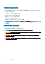
Information symbols

This book uses the following information symbols:

NOTE: 

The Note icon signals important operational information.

CAUTION: 

The Caution icon signals information about situations that could result in 

equipment damage or loss of data.

WARNING: 

The Warning icon signals information about hardware handling that 

could result in injury.

WARNING: 

The ESD Warning icon requires that you take electrostatic precautions 

when handling the device.

6

About this guide

Summary of Contents for EMC S4112-ON Series

Page 1: ...S4112 ON Series Setup Guide ...

Page 2: ...amage to hardware or loss of data and tells you how to avoid the problem WARNING A WARNING indicates a potential for property damage personal injury or death 2018 Dell Inc or its subsidiaries All rights reserved Dell EMC and other trademarks are trademarks of Dell Inc or its subsidiaries Other trademarks may be trademarks of their respective owners 2018 10 Rev A01 ...

Page 3: ... Storing components 10 3 S4112 ON Series Installation 11 Unpack 11 Ground cable 12 Rack or cabinet installation 13 Rack mount safety considerations 13 Half RU front rack installation 14 Switch installation 17 Switch removal 18 DC power connections 19 Optics installation 21 Optics removal 21 Switch power up 22 Power up sequence 22 After system installation 22 4 Specifications 23 Contents 3 ...

Page 4: ...Chassis physical design 23 5 Support 26 4 Contents ...

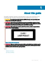
Page 5: ...ad this guide before you install and power up this equipment This equipment contains two power cords Disconnect both power cords before servicing WARNING This equipment contains optical transceivers which comply with the limits of Class 1 laser radiation Figure 1 Class 1 laser product tag WARNING When no cable is connected visible and invisible laser radiation may be emitted from the aperture of t...

Page 6: ...cent documentation see Dell EMC support www dell com support Information symbols This book uses the following information symbols NOTE The Note icon signals important operational information CAUTION The Caution icon signals information about situations that could result in equipment damage or loss of data WARNING The Warning icon signals information about hardware handling that could result in inj...

Page 7: ...ponents Topics Site selection Cabinet placement Rack mounting Switch ground Fans and airflow Power Storing components Site selection Install your equipment in restricted access areas A restricted access area is one where service personnel can only gain access using a special tool lock key or other means of security The authority responsible for the location controls access to the restricted area E...

Page 8: ...ratures see Specifications Cabinet placement Install the S4112 ON Series switch only in indoor cabinets designed for use in a controlled environment Do not install the S4112 ON Series switch in outside cabinets For cabinet placement requirements see Site selection The cabinet must meet minimum size requirements Airflow must be in accordance with the Electronic Industries Alliance EIA standard Ensu...

Page 9: ...ff the fans Power To connect the switch to the applicable power source use the appropriate power cable An AC power cable is included with the switch When installing AC or DC switches follow the requirements of the National Electrical Code ANSI NFPA 70 where applicable The switch is powered up when the power cable is connected between the switch and the power source CAUTION Always disconnect the po...

Page 10: ... from 40 to 65 C 40 to 149 F Store on a dry surface or floor away from direct sunlight heat and air conditioning ducts Store in a dust free environment NOTE ESD damage can occur when components are mishandled Always wear an ESD preventive wrist or heel ground strap when handling the switch and its accessories After you remove the original packaging place the S4112 ON Series switch and its componen...

Page 11: ...switch and its components As with all electrical devices of this type take all the necessary safety precautions to prevent injury when installing this switch Topics Unpack Ground cable Rack or cabinet installation Half RU front rack installation Switch installation DC power connections Optics installation Switch power up After system installation Unpack NOTE Before unpacking the switch inspect the...

Page 12: ...dicated ground wire NOTE For a DC powered switch the only way to safely ground your switch is to attach a dedicated ground wire The ground lug kit ships in a plastic bag placed with the other accessories inside the shipping box The ground lug bracket screws ship attached to the switch Before you install the DC switch in the dual tray attach the ground lug and bracket to the switch using the includ...

Page 13: ...installation ears are not a suitable grounding point Rack or cabinet installation You may either place the switch on a rack shelf or mount the switch directly into a 19 wide EIA 310 E compliant rack The dual tray mounting rails ship with the dual tray not the switch WARNING This guide is a condensed reference Read the safety instructions in your Safety Environmental and Regulatory information book...

Page 14: ...pment Pay particular attention to the supply connections other than the direct connections to the branch circuit for example use of power strips Do not mount the equipment with the fan panel facing in the downward position Half RU front rack installation The dual tray mounting rails ship with the dual tray not with the switch You must supply eight rack mount screws for this four post installation ...

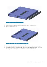
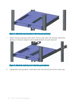
Page 15: ...other side Figure 3 Attach the dual tray and rack mounting rails 5 Install the dual tray inside the four post rack Rack mount screws are not included 6 Attach the front dual tray switch rails to the four post rack from the front Secure the dual tray to the rack using two user supplied screws for each rack post S4112 ON Series Installation 15 ...

Page 16: ...ils to the four post rack from the rear Secure the dual tray to the rack using two user supplied screws for each rack post Figure 5 Attach the dual tray rear to the four post rack rear 8 Tighten all mounting screws to securely mount the dual tray into the four post rack 16 S4112 ON Series Installation ...

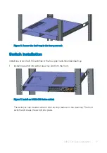
Page 17: ...es in the four post rack mounted dual tray 1 Install one switch into either dual tray slot from the front Figure 7 Install an S4112 ON Series switch The switch is fully inserted when it hits the stop feature on the dual tray The front switch latch snaps the switch into place S4112 ON Series Installation 17 ...

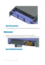
Page 18: ...ond switch in the open dual tray slot Switch removal 1 Remove a switch from the dual tray from the front of the four post rack 2 Push the front switch latches according to the latch arrows and pull out the switch Figure 9 S4112 ON Series release latches 18 S4112 ON Series Installation ...

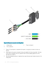
Page 19: ...Figure 10 S4112 ON Series release arrow DC power connections Each DC PSU comes with a connector cable One cable is provided for each DC PSU S4112 ON Series Installation 19 ...

Page 20: ...wer connector s wires as shown 2 Insert each of the power connector s bare wire lengths into the wiring block The blue wire is 48V the black wire is the positive return and the yellow green wire is the ground wire as shown 3 Use a flat blade screwdriver to tighten the screws that secures the bare wires into the wiring block 20 S4112 ON Series Installation ...

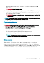
Page 21: ...s wear eye protection Never look directly into the end of a terminated or unterminated fiber or connector as it may cause eye damage 1 Position the optic so it is in the correct position The optic has a key that prevents it from being inserted incorrectly 2 Insert the optic into the port until it gently snaps into place NOTE When you cable the ports be sure not to interfere with the airflow from t...

Page 22: ...nk panels are installed if you do not install optional modules NOTE A US AC power cable is included for powering up an AC power supply You must order all other power cables separately NOTE ESD damage can occur if components are mishandled Always wear an ESD preventive wrist or heel ground strap when handling the switch and its components Power up sequence When the switch powers up the fans immedia...

Page 23: ...of battery Dispose of the batteries according to the manufacturer s instructions NOTE For RoHS information see Restricted Material Compliance Chassis physical design Table 1 Chassis physical design Parameter Specifications Height 1 75 inches 41 25 mm Width 8 2 inches 209 mm Depth 17 7 inches 450 mm Chassis weight with factory installed components S4112F ON 8 30 lbs 3 76 kg 2 PSUs and 3 fans S4112T...

Page 24: ... meters 3 117 feet Operating humidity 5 to 85 RH non condensing continuously 5 to 90 RH non condensing short term Short term is 1 of operational hours per year Storage temperature 40 to 65 C 40 to 149 F Storage humidity 5 to 95 non condensing Maximum thermal output S4112F ON 180W 614 BTU hr S4112T ON 200W 682 BTU hr Maximum operational altitude 10 000 feet 3 048 meters Maximum non operational alti...

Page 25: ...t 200 240V AC Maximum power consumption S4112F ON 180 W S4112T ON 200 W Typical power consumption S4112F ON 90 W S4112T ON 120 W Table 4 DC power requirements Parameter Specifications Minimum and maximum input voltage range 40V 72V DC 5A Max Maximum input current 40V 5A 48V 4 2A 72V 2 8A Start up VDC 39 0 1 5 V Start off VDC 37 5 1 5 V Specifications 25 ...

Page 26: ...e bottom of the web page and select your country from the drop down menu To obtain product specific information enter the 7 character service tag known as a luggage tag or 11 digit express service code of your switch and click Submit To view the chassis service tag or express service code pull out the tag or enter the show chassis command from the CLI To receive more technical support click Contac...

Reviews: