background image

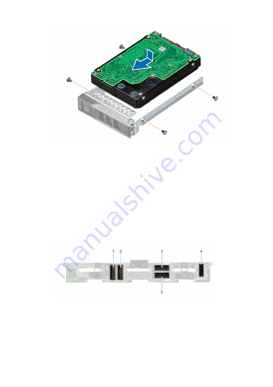
Figure 26. Installing a drive into drive carrier

Next steps

1.

Install the drive carrier

.

Drive backplane

Drive backplane details

Depending on the configuration, your system supports:

2.5-inch (x6) Universal backplane

2.5-inch (x6) SAS/SATA backplane

2.5-inch (x4) Universal backplane

Figure 27. 6 x 2.5-inch universal backplane

1. BP_DST_PA2 (PCIe cable connector)
2. BP_DST_PB1 (PCIe cable connector)
3. BP_DST_SA1 (SAS/SATA cable connector)
4. BP_PWR_1 (Power cable connector)
5. BP_DST_PA1 (PCIe cable connector )

36

Installing and removing system components

Summary of Contents for EMC PowerEdge MX750c

Page 1: ...Dell EMC PowerEdge MX750c Installation and Service Manual Part Number E04B Regulatory Type E04B003 May 2021 Rev A00 ...

Page 2: ...ential damage to hardware or loss of data and tells you how to avoid the problem WARNING A WARNING indicates a potential for property damage personal injury or death 2021 Dell Inc or its subsidiaries All rights reserved Dell EMC and other trademarks are trademarks of Dell Inc or its subsidiaries Other trademarks may be trademarks of their respective owners ...

Page 3: ...agement configuration validation 19 Minimum configuration to POST 19 Configuration validation 19 Error messages 20 Chapter 5 Installing and removing system components 21 Safety instructions 21 Before working inside your system 22 After working inside your system 22 Recommended tools 22 PowerEdge MX750c sled 22 Removing the sled from enclosure 22 Installing the sled into enclosure 24 Sled cover 25 ...

Page 4: ... sink module 61 Installing the processor into a processor and heat sink module 63 Installing the processor and heat sink module 66 PERC card 68 Removing the PERC card 68 Installing the PERC card 70 Removing the Jumbo PERC card 71 Installing the Jumbo PERC card 72 Optional IDSDM module 73 Removing the IDSDM module 73 Installing the IDSDM module 74 Removing the MicroSD card 75 Installing the MicroSD...

Page 5: ...onnectors 104 System board connectors 104 System board jumper settings 105 Disabling a forgotten password 105 Chapter 8 System diagnostics and indicator codes 106 Power button LED 106 System health and system ID indicator codes 106 Drive indicator codes 107 Using system diagnostics 107 Dell Embedded System Diagnostics 107 Chapter 9 Getting help 109 Recycling or End of Life service information 109 ...

Page 6: ...ument provides an overview about the system information about installing and replacing components technical specifications diagnostic tools and guidelines to be followed while installing certain components 1 6 About this document ...

Page 7: ...more information see the Dell EMC PowerEdge MX750c Technical Specifications on the product documentation page NOTE The Dell EMC PowerEdge MX750c is compatible with the Dell EMC PowerEdge MX7000 enclosure running OME Modular 1 30 or higher For more information about the enclosure see the Installation and Service Manual for the PowerEdge MX7000 at www dell com poweredgemanuals Topics Front view of t...

Page 8: ... direct port 3 Drives 4 Release handle 5 Release handle button 6 Information tag 7 System health and System ID indicator 8 Power button NOTE For more information see the Dell EMC PowerEdge MX750c Technical Specifications on the product documentation page 8 Dell EMC PowerEdge MX750c system overview ...

Page 9: ...5 Release handle 6 Release handle button 7 Information tag 8 System health and System ID indicator 9 Power button Inside the system NOTE Components that are hot swappable have orange touch points and the components that are not hot swappable have blue touch points Dell EMC PowerEdge MX750c system overview 9 ...

Page 10: ...formation tag is located on the front of the system that includes system information such as Service Tag Express Service Code Manufacture date NIC MAC address QRL label and so on Figure 4 Locating Service Tag of your system 1 Information tag 2 Service tag The Mini Enterprise Service Tag MEST label is located on the rear of the system that includes Service Tag ST Express Service Code Exp Svc Code a...

Page 11: ...System information label Figure 5 Mechanical overview Dell EMC PowerEdge MX750c system overview 11 ...

Page 12: ...Figure 6 Memory overview 12 Dell EMC PowerEdge MX750c system overview ...

Page 13: ...Figure 7 System board Figure 8 Jumper settings Dell EMC PowerEdge MX750c system overview 13 ...

Page 14: ...Figure 9 Quick Resource Locator Figure 10 System tasks 14 Dell EMC PowerEdge MX750c system overview ...

Page 15: ...ured on the OME For more information see the OME Modular User s Guide at https www dell com poweredgemanuals For more information about setting up the system see the Getting Started Guide that is shipped with your system NOTE For information about managing the basic settings and features of the system see the Dell EMC PowerEdge MX750c BIOS and UEFI Reference Guide on the product documentation page...

Page 16: ...roduct Support page of your system Documentation NOTE To determine the most recent iDRAC release for your platform and for latest documentation version see KB article https www dell com support article sln308699 OME Modular Dell OpenManagement Enterprise Modular User s Guide at https www dell com openmanagemanuals Dell OpenManage Enterprise Dell OpenManage Enterprise Modular Documentation NOTE To ...

Page 17: ...ine the most recent iDRAC release for your platform and for latest documentation version see KB article at https www dell com support article sln308699 Lifecycle Controller Lifecycle Controller User s Guide at https www dell com idracmanuals or for system specific Lifecycle Controller User s Guide go to https www dell com poweredgemanuals Product Support page of your system Documentation Dell reco...

Page 18: ...to https www dell com poweredgemanuals Product Support page of your system Documentation NOTE To determine the most recent iDRAC release for your platform and for latest documentation version see https www dell com support article sln308699 Downloading drivers and firmware It is recommended that you download and install the latest BIOS drivers and systems management firmware on the system Prerequi...

Page 19: ...red in a table maintained by iDRAC One or more sensors are assigned to each of the configuration elements During POST any configuration validation error is logged in the System Event Log SEL LifeCycle LC log The reported events are categorized in the configuration validation error table Table 5 Configuration validation error Error Description Possible cause and recommendations Example Config Error...

Page 20: ...he message is observed in the System Configuration Check operation Recommended Response Action Do the following and retry the operation 1 Disconnect the input power 2 Check for proper cable connection and component placement If the issue persists contact the service provider Category System Health HWC Hardware Config Severity Critical Trap EventID 2329 Table 7 Error message HWC8011 Error code HWC8...

Page 21: ...be done by a certified service technician You should only perform troubleshooting and simple repairs as authorized in your product documentation or as directed by the online or telephone service and support team Damage due to servicing that is not authorized by Dell is not covered by your warranty Read and follow the safety instructions that are shipped with your product NOTE It is recommended tha...

Page 22: ...onnect the peripherals and connect the system to the electrical outlet and then power on the system Recommended tools You need the following tools to perform the removal and installation procedures Phillips 1 screwdriver Phillips 2 screwdriver Torx T30 screwdriver 5 mm hex nut screwdriver Plastic scribe 1 4 inch flat blade screwdriver Wrist grounding strap connected to the ground ESD mat PowerEdge...

Page 23: ... you shut down the sled before removal Figure 11 Removing the sled from enclosure 3 Install the I O connector cover on the sled CAUTION To protect the I O connector pins install the I O connector cover every time a sled is removed from the enclosure Figure 12 Installing the I O connector cover on sled Installing and removing system components 23 ...

Page 24: ...ve the I O connector cover from the I O connector s and store for future use CAUTION To protect the I O connector pins install the I O connector cover every time a sled is removed from the enclosure Figure 13 Removing the I O connector cover from sled NOTE The color of the I O connector cover may differ 2 Press the blue release button on the sled to release the sled handle 3 Holding the sled with ...

Page 25: ...y guidelines listed in the Safety instructions 2 Power off the sled 3 Remove the sled from the enclosure 4 Place the sled on the flat surface with the top cover facing upwards Steps 1 Press the blue release tab and slide the cover towards the rear of the system 2 Lift the cover away from the system Installing and removing system components 25 ...

Page 26: ...in the Safety instructions 2 Ensure that all internal cables are connected and routed properly and no tools or extra parts are left inside the system Steps 1 Align the tabs on the system cover with the guide slots on the system 2 Slide the cover towards the front of the system until it locks in to place 26 Installing and removing system components ...

Page 27: ...Figure 16 Installing the sled cover Next steps 1 Follow the procedure listed in After working inside your system Installing and removing system components 27 ...

Page 28: ...de your system Steps Holding the air shroud at both ends lift the air shroud out of the system Figure 17 Removing the air shroud Next steps 1 Replace the air shroud Installing the air shroud Prerequisites 1 Follow the safety guidelines listed in the Safety instructions 2 Follow the procedure listed in Before working inside your system Steps 1 Align the slot on the air shroud with the tabs on the c...

Page 29: ...Figure 18 Installing the air shroud Next steps 1 Follow the procedure listed in After working inside your system Installing and removing system components 29 ...

Page 30: ... module blank away from the system NOTE The numbers on the image do not depict the exact steps The numbers are for representation of sequence Figure 19 Removing the processor and memory module blank Next steps 1 Replace the processor and memory module blank Installing the processor and memory module blank Prerequisites 1 Follow the safety guidelines listed in the Safety instructions 2 Follow the p...

Page 31: ... the ejectors firmly click into place Next steps 1 Follow the procedure listed in After working inside your system Drives Removing a drive blank Prerequisites 1 Follow the safety guidelines listed in the Safety instructions CAUTION To maintain proper system cooling drive blanks must be installed in all empty drive slots Steps Press the release button and slide the drive blank out of the drive slot...

Page 32: ...e Figure 22 Installing drive blank Removing the drive carrier Prerequisites 1 Follow the safety guidelines listed in the Safety instructions 2 Using the management software prepare the drive for removal If the drive is online the green activity or fault indicator blinks while the drive is powering off When the drive indicators are off the drive is ready for removal For more information see the doc...

Page 33: ...e the system is running see the documentation for the storage controller card to ensure that the host adapter is configured correctly to support drive removal and insertion CAUTION Combining SAS and SATA drives in the same RAID volume is not supported CAUTION When installing a drive ensure that the adjacent drives are fully installed Inserting a drive carrier and attempting to lock its handle next...

Page 34: ...arrier release handle to lock the drive in place Figure 24 Installing drive carrier Removing the drive from the drive carrier Prerequisites 1 Follow the safety guidelines listed in the Safety instructions 2 Remove the drive carrier Steps 1 Using the Phillips 1 screwdriver remove the screws from the slide rails on the drive carrier NOTE If the hard drive or SSD carrier has Torx screw use Torx 6 for...

Page 35: ...rrier ensure that the screws are torqued to 4 in lbs Steps 1 Insert the drive into the drive carrier with the drive connector facing towards the rear of the carrier 2 Align the screw holes on the drive with the screw holes on the drive carrier 3 Using the Phillips 1 screwdriver secure the drive to the drive carrier with the screws NOTE If the hard drive or SSD carrier has Torx screw use Torx 6 for...

Page 36: ...tem supports 2 5 inch x6 Universal backplane 2 5 inch x6 SAS SATA backplane 2 5 inch x4 Universal backplane Figure 27 6 x 2 5 inch universal backplane 1 BP_DST_PA2 PCIe cable connector 2 BP_DST_PB1 PCIe cable connector 3 BP_DST_SA1 SAS SATA cable connector 4 BP_PWR_1 Power cable connector 5 BP_DST_PA1 PCIe cable connector 36 Installing and removing system components ...

Page 37: ...UTION Note the number of each drive and temporarily label them before you remove the drive so that you can reinstall them in the same location NOTE The procedure to remove the backplane is similar for all backplane configurations 1 Follow the safety guidelines listed in Safety Instructions 2 Follow the procedure listed in Before working inside your system 3 Disconnect the drive backplane cables fr...

Page 38: ...emove all the drives Steps 1 Verify backplane connector pins are not bent and then connect the signal cable to the backplane 2 Align the guide pins on the backplane with the guides on the sled 3 Insert the backplane into the guides and lower the backplane firmly until it is fully seated NOTE To install the backplane ensure the two pins on the backplane tab seat into the two slots on the system cha...

Page 39: ...and signal cable connections are fully seated to the backplane and system board 2 Connect the integrated cable to the backplane and system board if there is no PERC card installed in the system 3 Install all the drives 4 Follow the procedure listed in After working inside the system Installing and removing system components 39 ...

Page 40: ...ble marking BP PA1 SL1_CPU1_PA1 signal connector on the system board cable marking MB SL1 BP_DST_SA1 backplane SATA connector cable marking BP SA1 SL6_PCH_SA1 signal connector on the system board cable marking MB SL6 BP_DST_PB1 backplane PCIe 2 connector cable marking BP PB1 SL2_CPU1_PB1 signal connector on the system board cable marking MB SL2 BP_DST_PA2 backplane PCIe 3 connector cable marking B...

Page 41: ...L_SRC_PA1 PCIe connector of H755 MX controller card cable marking CTRL_PA1 BP_DST_PB1 backplane PCIe 2 connector cable marking BP PB1 CTRL_SRC_PA1 PCIe connector of H755 MX controller card cable marking CTRL_PA1 BP_DST_PA2 backplane PCIe 3 connector cable marking BP PA2 CTRL_SRC_PA2 PCIe connector of H755 MX controller card cable marking CTRL_PA2 Figure 34 SATA cabling diagram of configuration 5 6...

Page 42: ...agram of configuration 6 6 x 2 5 inch SAS SATA backplane with HBA350i MX Table 11 Connector descriptions for SAS with HBA350i MX From To BP_PWR_1 backplane power connector SIG_PWR_0 system board power connector BP_DST_SA1 backplane SAS connector cable marking BP SA1 CTRL_SRC_SA1 SAS connector of HBA350i MX controller card cable marking CTRL_SA1 Figure 36 SAS cabling diagram of configuration 6 6 x ...

Page 43: ...d cable marking CTRL_SA1 Figure 37 SAS cabling diagram of configuration 7 6 x 2 5 inch SAS SATA backplane with H745P MX Jumbo PERC Table 13 Connector descriptions for SAS with H745P MX From To BP_PWR_1 backplane power connector SIG_PWR_0 system board power connector BP_DST_SA1 backplane SAS connector cable marking BP SA1 CTRL_SRC_SA1 SAS connector of H745P MX controller card cable marking CTRL_SA1...

Page 44: ...e marking BP_PA1 SL1_CPU1_PA1 signal connector on the system board cable marking MB SL1 BP_DST_SA1 backplane SAS connector cable marking BP SA1 CTRL_SRC_SA1 SAS connector of HBA350i MX controller card cable marking CTRL_SA1 BP_DST_PB1 backplane PCIe 2 connector cable marking BP PB1 SL2_CPU1_PB1 signal connector on the system board cable marking MB SL2 Figure 39 SAS PCIe cabling diagram of configur...

Page 45: ...arking MB SL2 Figure 40 SAS PCIe cabling diagram of configuration 10 4 x 2 5 inch Universal backplane with H745P MX Jumbo PERC on board PCIe Table 16 Connector descriptions for SAS with H745P MX on board PCIe From To BP_PWR_1 backplane power connector SIG_PWR_0 system board power connector BP_DST_PA1 backplane PCIe 1 connector cable marking BP PA1 SL1_CPU1_PA1 signal connector on the system board ...

Page 46: ...onnector cable marking BP PA1 SL1_CPU1_PA1 signal connector on the system board cable marking MB SL1 BP_DST_SA1 backplane SAS connector cable marking BP SA1 SL6_PCH_SA1 signal connector on the system board cable marking MB SL6 BP_DST_PB1 backplane PCIe 2 connector cable marking BP PB1 SL2_CPU1_PB1 signal connector on the system board cable marking MB SL2 Figure 42 PCIe cabling diagram of configura...

Page 47: ...he backplane CAUTION Temporarily label drives before you remove the drives so that you can replace them in the same slots NOTE Observe the routing of the cables on the chassis as you remove them from the system You must route these cables properly when you replace them to prevent the cables from being pinched or crimped 1 Follow the safety guidelines listed in the Safety instructions 2 Follow the ...

Page 48: ...ons 2 Follow the procedure listed in Before working inside your system 3 Disconnect the drive backplane cables from the connectors on the system board Steps 1 Place the drive cage into the system aligning with the screw holes on the system 2 Using the Phillips 1 screwdriver tighten the screws to secure the drive cage in place 48 Installing and removing system components ...

Page 49: ...orking inside your system 3 Remove all the drives 4 Remove the drive cage Steps 1 Releasing the blue latches pull the blue strap to disconnect the control panel cable connected to the system board 2 Using the Phillips 1 screwdriver remove the screws that secure the control panel to the system 3 Holding the control panel remove the control panel along with the cable from the system NOTE The numbers...

Page 50: ...r system 3 Remove all the drives 4 Remove the drive cage Steps 1 Align and insert the control panel in the slot on the system 2 Connect the control panel cable to the connector on the system board 3 Using a Phillips 1 screwdriver tighten the screws that secure the control panel to the system NOTE The numbers on the image do not depict the exact steps The numbers are for representation of sequence ...

Page 51: ...set per processor Each 16 socket set is organized into eight channels Eight memory channels are allocated to each processor In each channel the release tabs of the first socket are marked white and the second socket black Memory channels are organized as follows Table 19 Memory channels Processor Channel A Channel B Channel C Channel D Channel E Channel F Channel G Channel H Processor 1 Slots A1 a...

Page 52: ...2933 MT s depending on the following factors System profile selected for example Performance Optimized or Custom can be run at high speed or lower Maximum supported DIMM speed of the processors Maximum supported speed of the DIMMs NOTE MT s indicates DIMM speed in MegaTransfers per second NOTE Fault Resilient Memory Non Uniform Memory Access is supported The system supports Flexible Memory Configu...

Page 53: ...TE If two different Intel Optane PMem 200 Series capacities are mixed an F1 F2 warning is displayed as the configuration is not supported Intel Optane PMem 200 Series can be mixed with RDIMM LRDIMM and 3DS LRDIMM Mixing of DDR4 DIMM types RDIMM LRDIMM and 3DS LRDIMM within channels for Integrated Memory Controller iMC or across sockets are not supported Mixing of Intel Optane PMem 200 Series opera...

Page 54: ...uration 4 8 x RDIMMs 4 x Intel Optane PMem 200 Series Processor1 A1 2 3 4 5 6 7 8 Processor2 B1 2 3 4 5 6 7 8 Processor1 A9 10 11 12 Processor2 B9 10 11 12 Configuration 5 8 x RDIMMs 8 x Intel Optane PMem 200 Series Processor1 A1 2 3 4 5 6 7 8 Processor2 B1 2 3 4 5 6 7 8 Processor1 A9 10 11 12 13 14 15 16 Processor2 B9 10 11 12 13 14 15 16 Configuration 6 12 x RDIMMs 2 x Intel Optane PMem 200 Seri...

Page 55: ...BPS capacity GB Total Standard Memory Capacity GB Total PM Capacity GB Supported Modes 6 1 16 128 96 128 AD 6 1 32 128 192 128 AD 6 1 64 128 384 128 AD 6 1 128 128 768 128 AD 6 1 16 256 96 256 AD 6 1 32 256 192 256 AD 6 1 64 256 384 256 AD 6 1 128 256 768 256 AD 6 1 16 512 96 512 AD 6 1 32 512 192 512 AD 6 1 64 512 384 512 AD 6 1 128 512 768 512 AD Table 25 Intel Optane PMem 200 Series Configurati...

Page 56: ...l PM Capacity GB Supported Modes 8 4 16 128 128 512 MM or AD 8 4 32 128 256 512 AD 8 4 64 128 512 512 AD 8 4 128 128 1024 512 AD 8 4 16 256 128 1024 MM or AD 8 4 32 256 256 1024 MM or AD 8 4 64 256 512 1024 AD 8 4 128 256 1024 1024 AD 8 4 16 512 128 2048 MM or AD 8 4 32 512 256 2048 MM or AD 8 4 64 512 512 2048 MM or AD 8 4 128 512 1024 2048 AD Table 27 Intel Optane PMem 200 Series Configuration 5...

Page 57: ... 128 384 256 AD 12 2 64 128 768 256 AD 12 2 128 128 1536 256 AD 12 2 16 256 192 512 AD 12 2 32 256 384 512 AD 12 2 64 256 768 512 AD 12 2 128 256 1536 512 AD 12 2 16 512 192 1024 AD 12 2 32 512 384 1024 AD 12 2 64 512 768 1024 AD 12 2 128 512 1536 1024 AD Removing a memory module Prerequisites 1 Follow the safety guidelines listed in Safety instructions 2 Follow the procedure listed in Before work...

Page 58: ...e blanks must be installed in any memory socket that is not occupied Remove memory module blanks only if you intend to install memory modules in those sockets Steps 1 Locate the appropriate memory module socket CAUTION Handle each memory module only by the card edges ensuring not to touch the middle of the memory module or metallic contacts 2 If a memory module is installed in the socket remove it...

Page 59: ...he updated capacity of the installed memory 4 If the System Memory Size is incorrect one or more of the memory modules may not be installed properly Ensure that the memory modules are firmly seated in their sockets 5 Run the system memory test in the system diagnostics Processor and heat sink module Removing a processor and heat sink module Prerequisites 1 Follow the safety guidelines listed in Sa...

Page 60: ...Return to the first screw to loosen it completely 2 Set the Anti Tilt wires to the unlocked position inward position Figure 50 Loosening the screws and set the Anti Tilt wires to the unlocked position 3 Lift the processor and heat sink module PHM from the system and set the PHM aside with the processor side facing up 60 Installing and removing system components ...

Page 61: ...le PHM WARNING The heat sink may be hot to touch for some time after the system has been powered down Allow the heat sink to cool before removing it CAUTION An expected CMOS battery loss or CMOS checksum error message may be displayed during the first instance of powering on the system after replacing the processor or system board To resolve this issue go to setup option to configure the system se...

Page 62: ...n the TIM break lever back to its original position 4 Using your thumb and index finger first hold the retaining clip release tab at the pin 1 connector pull out the tip of the retaining clip release tab and then lift the retaining clip partially from the heat sink 5 Repeat the procedure at the remaining three corners of the retaining clip 6 After all the corners are released from the heat sink li...

Page 63: ...ssor tray NOTE Ensure that the pin 1 indicator on the processor tray is aligned with the pin 1 indicator on the processor 2 Place the processor retaining clip on top of the processor that is in the processor tray aligning pin 1 indicator on the processor NOTE Ensure that the pin 1 indicator on the retaining clip is aligned with the pin 1 indicator on the processor before placing the retaining clip...

Page 64: ...he processor is securely latched to the processor retaining clip Figure 56 Press the retaining clip on the four sides 4 If you are using an existing heat sink remove the thermal grease on the heat sink by using a clean lint free cloth 5 Use the thermal grease syringe included with your processor kit to apply the grease in a thin spiral on the bottom of the heat sink 64 Installing and removing syst...

Page 65: ...he base of heat sink Figure 58 Remove the Thermal Interface Material TIM protective film 7 Place the heat sink on the processor and press the heat sink until the retaining clip locks onto the heat sink at all the four corners CAUTION To avoid damaging the fins on the heat sink do not press down on the heat sink fins NOTE Ensure that the pin 1 indicator on the heat sink is aligned with the pin 1 in...

Page 66: ...e the processor The heat sink is necessary to maintain proper thermal conditions 1 Follow the safety guidelines listed in Safety instructions 2 Follow the procedure listed in the Before working inside the system 3 Remove the air shroud 4 If installed remove the processor dust cover Steps 1 Set the Anti Tilt wires to the unlocked position on the heat sink inward position 2 Align the pin 1 indicator...

Page 67: ... the locked position outward position and then using the Torx T30 screwdriver tighten the screws 8 in lbf on the heat sink in the order below a Tighten the first screw three turns b Tighten the screw diagonally opposite to the screw you tighten first c Repeat the procedure for the remaining two screws d Return to the first screw to tighten it completely Installing and removing system components 67...

Page 68: ...ts on the system board for PERC cards Removing the PERC card Prerequisites 1 Follow the safety guidelines listed in Safety Instructions 2 Follow the procedure listed in Before working inside your system 3 Disconnect the cable connected to the PERC card Steps 1 Pull the blue pull tag to lift the lever up on the PERC card 2 Holding the blue pull tag lift the PERC card out of the system 68 Installing...

Page 69: ...gure 62 Removing the PERC card HBA350i MX Figure 63 Removing the PERC card H755 MX Next steps 1 Follow the procedure listed in After working inside your system Installing and removing system components 69 ...

Page 70: ... the blue pull tag to raise the lever up on the PERC card 2 Align the connector on the PERC card with the connector on the system board 3 Align the guides on the PERC card with the slots on the system 4 Press the PERC card firmly until it is fully seated 5 Close the lever on the PERC card Figure 64 Installing the PERC card HBA350i MX 70 Installing and removing system components ...

Page 71: ...es listed in the Safety instructions 2 Follow the procedure listed in the Before working inside your system 3 Disconnect the cable connected to the Jumbo PERC card Steps 1 Pull the blue pull tag to raise the lever up on the Jumbo PERC card 2 Holding the blue pull tag lift the Jumbo PERC card away from the system 3 Install the connector cap on the I O connector of the Jumbo PERC card Installing and...

Page 72: ... instructions 2 Follow the procedure listed in the Before working inside your system NOTE Jumbo PERC card is supported only on dual processor configuration Steps 1 Remove the connector cap on the I O connector from the Jumbo PERC card 2 Pull the blue pull tag to raise the lever on the Jumbo PERC card 3 Align the Jumbo PERC card with the slots on the system board 4 Press the Jumbo PERC card firmly ...

Page 73: ...e IDSDM module Prerequisites 1 Follow the safety guidelines listed in the Safety instructions 2 Follow the procedure listed in the Before working inside your system 3 Remove the air shroud Steps Holding the blue tag lift the IDSDM card out of the system CAUTION To prevent damage to the IDSDM card you must not tilt the card while lifting it from the system board Installing and removing system compo...

Page 74: ...ollow the procedure listed in Before working inside your system CAUTION To prevent damage to the IDSDM card you must hold the card only by its edges Steps 1 Locate the IDSDM connector on the system board 2 Align the IDSDM card with the connector on the system board 3 Push the IDSDM card firmly until it is fully seated on the system board 74 Installing and removing system components ...

Page 75: ...ructions 2 Follow the procedure listed in the Before working inside your system 3 Remove the IDSDM module Steps 1 Locate the MicroSD card slot on the IDSDM module and press the card to partially release it from the slot 2 Hold the MicroSD card and remove it from the slot NOTE Temporarily label each MicroSD card with its corresponding slot number after removal Installing and removing system compone...

Page 76: ... your system ensure that the Internal SD Card Port is enabled in System Setup NOTE If reinstalling ensure that you install the MicroSD cards into the same slots based on the labels you had marked on the cards during removal Steps 1 Locate the MicroSD card connector on the IDSDM module Orient the MicroSD card appropriately and insert the contact pin end of the card into the slot NOTE The slot is ke...

Page 77: ...inside your system M 2 BOSS card Removing the M 2 BOSS card Prerequisites 1 Follow the safety guidelines listed in the Safety instructions 2 Follow the procedure listed in the Before working inside your system Steps Holding the blue tag lift the M 2 BOSS card out of the system Installing and removing system components 77 ...

Page 78: ...ety instructions 2 Follow the procedure listed in the Before working inside your system Steps 1 Align the M 2 BOSS card connector with the connectors on the system board and the guide on the M 2 BOSS card with the guiding slot on the system board 2 Press the touch point on the M 2 BOSS card firmly until it is fully seated 78 Installing and removing system components ...

Page 79: ...ites 1 Follow the safety guidelines listed in the safety instructions 2 Follow the procedure listed in the Before working inside your system Steps 1 Using the Phillips 1 screwdriver remove the screws that secure the M 2 SSD module to the M 2 BOSS card 2 Pull the M 2 SSD module to remove it from the M 2 BOSS card Installing and removing system components 79 ...

Page 80: ...structions 2 Follow the procedure listed in the Before working inside your system Steps 1 Align the M 2 SSD module at an angle with the M 2 BOSS card connector 2 Insert the M 2 SSD module firmly until it is fully seated in the M 2 BOSS card connector 3 Using the Phillips 1 screwdriver secure the M 2 SSD module on the M 2 BOSS card 80 Installing and removing system components ...

Page 81: ...r mini Mezz card connected to processor 2 Mezzanine card installation guidelines The following table describes the supported mezzanine cards Table 29 Mezzanine card riser configurations Mezzanine card category Description Slot priority Maximum cards Fl Ethernet Mezz Broadcom PCIe Gen4 Quad Port 25Gb NIC Mezzanine slot A or B populate A first 2 QLogic PCIe Gen3 QL41262 DP 25Gb CNA Mezzanine slot A ...

Page 82: ... 1 PERC 11 H755 MX PERC connector 1 Removing the Mezzanine card Prerequisites 1 Follow the safety guidelines listed in Safety Instructions 2 Follow the procedure listed in Before working inside your system Steps 1 Use the Phillips 2 screwdriver loosen the captive screws that secure the Mezzanine card to the system 2 Lift the Mezzanine card out of the sled NOTE To prevent damage to Mezzanine card y...

Page 83: ...low the procedure listed in Before working inside your system NOTE Mezzanine B card is supported only on dual processor configuration Steps 1 Align the connector on the Mezzanine card with the connector on the system board 2 Place the Mezzanine card on the connector and press the blue touch point firmly until it is fully seated 3 Using the Phillips 2 screwdriver tighten the captive screws on the M...

Page 84: ...gure 78 Installing the Mezzanine A card Figure 79 Installing the Mezzanine B card Next steps 1 Follow the procedure listed in After working inside your system 84 Installing and removing system components ...

Page 85: ...ed in mini Mezzanine socket Steps 1 Pull the blue pull tag to lift the lever up of the mini Mezzanine card 2 Holding the lever and the edge of the mini Mezzanine card lift the mini Mezzanine card from the system Figure 80 Removing the mini Mezzanine card HBA330 MMZ NOTE Install the connector cap on the I O connector of the mini Mezzanine card when not installed on system board Next steps 1 Follow ...

Page 86: ...e lever on the mini Mezzanine card Next steps 1 Follow the procedure listed in After working inside your system Removing the mini Mezzanine card blank Prerequisites CAUTION To ensure proper system cooling the mini Mezzanine blank must be installed in the mini Mezzanine socket NOTE The removal of the blank is recommended only if you intend to install a mini Mezzanine card in the socket 1 Follow the...

Page 87: ...ini Mezzanine card blank Prerequisites 1 Follow the safety guidelines listed in Safety Instructions 2 Follow the procedure listed in Before working inside your system Steps 1 Align the slot on the blank with the guiding pin on the system 2 Insert and press the blank firmly until it is fully seated Installing and removing system components 87 ...

Page 88: ...ce with other components in the server the maximum permissible dimensions of the USB memory key 15 9 mm width x 57 15 mm length x 7 9 mm height 1 Follow the safety guidelines listed in the Safety instructions 2 Follow the procedure listed in the Before working inside your system Steps 1 Locate the USB port or USB memory key on the system board 2 If installed remove the USB memory key from the USB ...

Page 89: ...into the USB port Figure 85 Installing the internal USB memory key Next steps 1 While booting press F2 to enter System Setup and verify that the system detects the USB memory key 2 Follow the procedure listed in After working inside your system Installing and removing system components 89 ...

Page 90: ...fety guidelines listed in the Safety instructions 2 Follow the procedure listed in the Before working inside your system Steps 1 To remove the battery a Use a plastic scribe to pry out the system battery CAUTION To avoid damage to the battery connector you must firmly support the connector while installing or removing a battery Figure 86 Removing the system battery 2 To install a new system batter...

Page 91: ...erequisites CAUTION If you are using the Trusted Platform Module TPM with an encryption key you may be prompted to create a recovery key during program or System Setup Be sure to create and safely store this recovery key If you replace this system board you must supply the recovery key when you restart your system or program before you can access the encrypted data on your drives 1 Follow the safe...

Page 92: ...e screws that secure the Mezz card brackets to the system board 2 Holding the brackets by the edges lift the brackets out of the system 3 Using the Phillips 2 screwdriver remove the screws that secure the system board to the chassis 4 Lift the system board out of the chassis Figure 88 Removing the system board Next steps 1 Replace the system board Installing the system board Prerequisites NOTE Bef...

Page 93: ... system board into the chassis Figure 89 Installing the system board 3 Holding the Mezz card brackets by its edges lower the brackets into the system board 4 Using the Phillips 2 screwdriver tighten the screws that secure the system board to the chassis 5 Using the Phillips 2 screwdriver tighten the screws that secure the Mezz card brackets to the system board Next steps 1 Replace the following co...

Page 94: ... restore your service tag license UEFI configuration and the system configuration data after replacing the system board All data is backed up in a backup flash device automatically If BIOS detects a new system board and the service tag in the backup flash device BIOS prompts the user to restore the backup information About this task Below is a list of options available Restore the service tag lice...

Page 95: ...ve been securely transferred Removing the TPM Steps 1 Locate the TPM connector on the system board 2 Press to hold the module down and remove the screw using the security Torx 8 bit shipped with the TPM module 3 Slide the TPM module out from its connector 4 Push the plastic rivet away from the TPM connector and rotate it 90 counterclockwise to release it from the system board 5 Pull the plastic ri...

Page 96: ... System BIOS System Security Settings 3 From the TPM Security option select On with Preboot Measurements 4 From the TPM Command option select Activate 5 Save the settings 6 Restart your system Initializing the TPM 2 0 for users Steps 1 While booting your system press F2 to enter System Setup 2 On the System Setup Main Menu screen click System BIOS System Security Settings 3 From the TPM Security o...

Page 97: ... column Backplane configuration in the table Figure 91 x6 universal backplane Figure 92 x4 universal backplane Figure 93 x6 SAS SATA backplane 2 Identify the current system configuration see column Upgrade from in the table and the upgrade to configuration see column Upgrade to in the table 3 Disconnect the card or cables see column Disconnect and remove card or cables from the connector in the ta...

Page 98: ...Table 31 Cables Cable name Cable connector name Cable image SATA cable MB SL6 BP SA1 SAS cable BP SA1 CTRL_SA1 PCIEA cable CTRL_ PA1 BP PA1 98 Upgrade Kits ...

Page 99: ...Cable connector name Cable image Jumbo SAS cable BP SA1 CTRL_SA1 PCIE1 cable MB SL1 BP PA1 PCIE2 cable MB SL2 BP PB1 PCIEB cable CTRL_PB1 BP PA2 Topics PERC H755 MX Upgrade kit PERC H745P MX Upgrade kit HBA350i Upgrade kit Upgrade Kits 99 ...

Page 100: ... BP SA1 H755 MX card SAS cable CTRL_SA1 BP SA1 Cable routing SAS PCIe cabling diagram of configuration 9 4 x 2 5 inch Universal backplane with H755 MX on board PCIe H755 MX NVME HW RAID SATA cable MB SL6 BP SA1 PCIE1 cable MB SL1 BP PA1 PCIE2 cable MB SL2 BP PB1 H755 MX card PCIEA cable CTRL_PA1 BP PA1 and BP PB1 Cable routing SATA cabling diagram of configuration 12 4 x 2 5 inch SATA SAS only bac...

Page 101: ...RL_SA1 H755 MX card SAS cable CTRL_SA1 BP SA1 Cable routing SAS cabling diagram of configuration 6 6 x 2 5 inch SAS SATA backplane with H755 MX PERC H745P MX Upgrade kit The below table provides the upgrade kit information about PERC H745P MX available After Point of Sale APOS Table 33 PERC H745P MX upgrade kit Backplane configuration Upgrade from Upgrade to Disconnect and remove card or cables fr...

Page 102: ...bout HBA350i available After Point of Sale APOS Table 34 HBA350i upgrade kit Backplane configuration Upgrade from Upgrade to Disconnect and remove card or cables from the connector cable marking Replace with the card or cables cable marking Refer to cabling configurations X4 Universal backplane Onboard SATA SWRAID NVME HBA350i SAS Controller Non RAID SATA cable MB SL6 BP SA1 HBA350i card SAS cable...

Page 103: ... Backplane configuration Upgrade from Upgrade to Disconnect and remove card or cables from the connector cable marking Replace with the card or cables cable marking Refer to cabling configurations with H755 MX on board PCIe Upgrade Kits 103 ...

Page 104: ...d connectors 1 Front I O connector 2 Backplane power SIG_PWR_0 3 DIMMs for processor 1 CPU 1 channels A B C D 4 Processor 1 CPU 1 5 DIMMs for processor 2 CPU 2 channels A B C D 6 Processor 2 CPU 2 7 MEZZ connector A MEZZ_A1 8 Internal USB INT_USB1_3 0 9 MEZZ connector B MEZZ_B1 10 Power connector 11 Jumbo PERC Mini MEZZ connector C Mini_MEZZ_C1 12 DIMMs for processor 2 CPU 2 channels E F G H 13 PC...

Page 105: ... should only perform troubleshooting and simple repairs as authorized in your product documentation or as directed by the online or telephone service and support team Damage due to servicing that is not authorized by Dell is not covered by your warranty Read and follow the safety instructions that are shipped with your product Steps 1 Power off the compute sled and remove the compute sled from cha...

Page 106: ...power supply units are active Slowly blinking System is performing powering on sequence and iDRAC is still booting NOTE When MX750c is installed in MX7000 the power button LED indicator display the status as off for one minute while the sled is initialized even if the sled is configured to power on automatically for example with an AC power recovery policy of On or Last After one minute if the sle...

Page 107: ...naged by Storage Spaces Direct Not all drive status indicators may be used Table 38 Drive indicator codes Drive status indicator code Condition Blinks green twice per second Indicates that the drive is being identified or preparing for removal Off Indicates that the drive is ready for removal NOTE The drive status indicator remains off until all drives are initialized after the system is powered o...

Page 108: ...ing the Embedded System Diagnostics from Boot Manager Run the Embedded System Diagnostics ePSA if your system does not boot Steps 1 When the system is booting press F11 2 Use the up arrow and down arrow keys to select System Utilities Launch Diagnostics 3 Alternatively when the system is booting press F10 select Hardware Diagnostics Run Hardware Diagnostics The ePSA Pre boot System Assessment wind...

Page 109: ... home 2 Select your country from the drop down menu on the lower right corner of the page 3 For customized support a Enter the system Service Tag in the Enter a Service Tag Serial Number Service Request Model or Keyword field b Click Search The support page that lists the various support categories is displayed 4 For general support a Select your product category b Select your product segment c Se...

Page 110: ...upport for your Dell EMC server storage and networking devices By installing and setting up a SupportAssist application in your IT environment you can receive the following benefits Automated issue detection SupportAssist monitors your Dell EMC devices and automatically detects hardware issues both proactively and predictively Automated case creation When an issue is detected SupportAssist automat...

Page 111: ...ur system remotely see the Integrated Dell Remote Access Controller User s Guide For information about understanding Remote Access Controller Admin RACADM subcommands and supported RACADM interfaces see the RACADM CLI Guide for iDRAC For information about Redfish and its protocol supported schema and Redfish Eventing implemented in iDRAC see the Redfish API Guide For information about iDRAC proper...

Page 112: ...ems management see the OpenManage Connections Enterprise Systems Management documents www dell com openmanagemanuals Working with the Dell PowerEdge RAID controllers For information about understanding the features of the Dell PowerEdge RAID controllers PERC Software RAID controllers or BOSS card and deploying the cards see the Storage controller documentation www dell com storagecontrollermanuals...

Reviews: