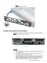
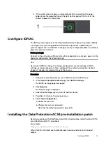


4. Use a Cat5e or Cat6 copper Ethernet cable to connect the iDRAC port (1) in
the lower left of the system chassis to the network.
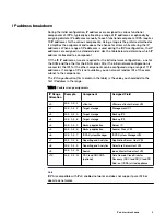
DP4400 ports
The following table provides the callout number and the type of port for the DP4400
ports in
Figure 1 DP4400 network and iDRAC connections
.
Table 2 DP4400 port types
Callout number
Port type
1
iDRAC
2
10 GbE (required)
3
10 GbE (required)
4
10 GbE (unused)
5
10 GbE (unused)
6
10 GbE (unused)
7
10 GbE (unused)
8
10 GbE (required)
9
10 GbE (required)
10
1 GbE
11
1 GbE (unused)
Note
Ports 2 and 9 are a vSwitch0 network team. Ports 3 and 8 are a vSwitch1 network
team and are used during appliance configuration.
Note
Ensure that the four required 10 GbE ports (2, 3, 8, and 9) are connected to the
access ports on the switch in your network.
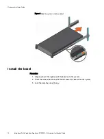
Connect the power cables and power on
Procedure
1. Connect the power supply units to the rack.
Note
Connect each PSU to a redundant AC power source. Redundant power sources
allow one AC source to fail or be serviced without impacting system operation.
Connect PSU 0 to one AC source, and PSU 1 to the other AC source.
The system may not power on automatically after plugging in the AC power
cords. The system identification button located on the rear of the chassis, on
the lower left-hand side illuminates blue when power is on.
Hardware Installation Guide
12
Integrated Data Protection Appliance DP4400
2.4
Hardware Installation Guide