


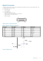
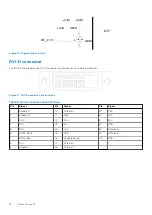
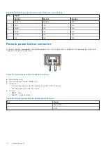
Digital I/O connector
The EGW-5200 provides eight channels of non-isolation digital input and eight channels of non-isolation digital output circuits,
with specifications and circuits as follows.
●
8-channel digital input
○
VIH: 2 V to 5.25 V
○
VIL: 0 V to 0.8 V
●
8-channel digital output
○
Output type: Open drain N-channel
○
MOSFET driver with internal pull high of 200 Ω resistance
○
Source/sink current for all channels: 24 mA
○
VOH: 2.4 V to 5 V
○
VOL: 0 V to 0.5 V
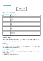
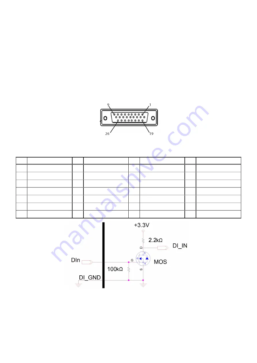
Figure 8. Digital I/O connector pin locations
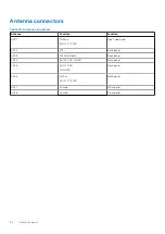
Table 7. Digital I/O connector pin definitions
Pin
Signal
Pin
Signal
Pin
Signal
Pin
Signal
1
DI0
8
DI7
15
N/C
22
DO3
2
DI1
9
GND
16
N/C
23
DO4
3
DI2
10
N/C
17
N/C
24
DO5
4
DI3
11
N/C
18
GND
25
DO6
5
DI4
12
N/C
19
DO0
26
DO7
6
DI5
13
N/C
20
DO1
-
-
7
DI6
14
N/C
21
DO2
-
-
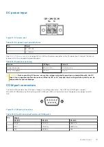
Figure 9. Digital input circuit
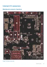
System Layout
15
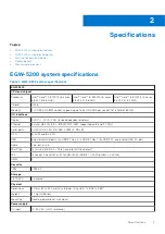
Summary of Contents for EGW-5200
Page 1: ...Dell EMC Edge Gateway 5200 User s Guide January 2022 Rev A01 ...
Page 31: ...Main Figure 27 BIOS screen Main tab BIOS Setup 31 ...
Page 32: ...Advanced Figure 28 BIOS screen Advanced tab 32 BIOS Setup ...
Page 33: ...CPU Configuration Figure 29 CPU Configuration top of screen BIOS Setup 33 ...
Page 47: ...NVMe Configuration Figure 41 NVMe Configuration BIOS Setup 47 ...
Page 51: ...Memory Configuration Figure 45 Memory Configuration BIOS Setup 51 ...
Page 54: ...PCH IO Configuration Figure 48 PCH IO Configuration 54 BIOS Setup ...
Page 56: ...Security Configuration Figure 50 Security Configuration 56 BIOS Setup ...
Page 57: ...M 2 Device Configuration Figure 51 M 2 Device Configuration BIOS Setup 57 ...
Page 58: ...Security Figure 52 BIOS screen Security tab 58 BIOS Setup ...
Page 64: ...Save and Exit Figure 57 BIOS screen Save and Exit tab 64 BIOS Setup ...
Page 65: ...Event logs Figure 58 BIOS screen Event logs tab BIOS Setup 65 ...