background image

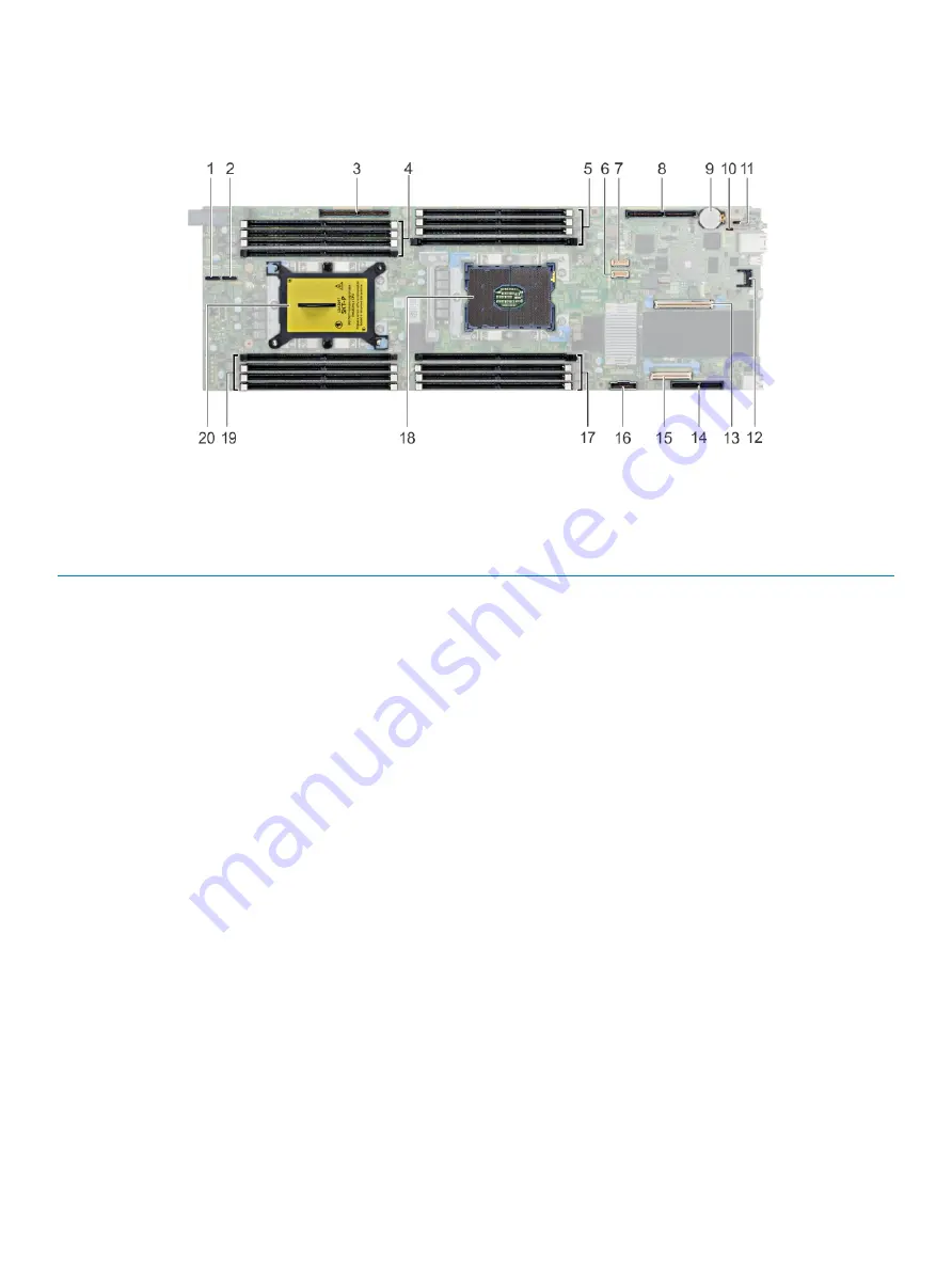
System board connectors

Figure 41. XC6420 system board connectors

Table 29. System Board Connectors and Description

Item

Connector

Description

1

PCIe B

NVMe B connector

2

PCIe A

NVMe A connector

3

PCIe Slot 5

Slot 5: x16 PCIe Gen3 from CPU 2

4

DIMM sockets (4)

DIMM B8, DIMM B4, DIMM B5, DIMM B6

5

DIMM sockets (4)

DIMM A8, DIMM A4, DIMM A5, DIMM A6

6

HFI_SB_1

Side band cable 1 for OCP

7

HFI_SB_2

Side band cable 2 for OCP

8

PCIe Slot 4

Slot 4: x16 PCIe Gen3 CPU 1

9

Batt

System battery

10

PWDCLR

Password clear jumper

11

NVRAMCLR

NVRAM clear jumper

12

PCIe Slot 3

Slot 3: x8 PCIe Gen3 from CPU 1

13

TPM

TPM connector

14

PCIe Slot 1

Slot 1: x8 PCIe Gen3 from CPU 1

15

PCIe Slot 2

Slot 2: x8 PCIe Gen3 from CPU 1

16

SATA_A

SATA cable connector

17

DIMM sockets (4)

DIMM A7, DIMM A1, DIMM A2, DIMM A3

18

CPU 1

CPU socket 1

19

DIMM sockets (4)

DIMM B7, DIMM B1, DIMM B2, DIMM B3

88

Jumpers and connectors 

Summary of Contents for E43S Series

Page 1: ...Dell EMC XC6420 Series Hyper Converged Appliance Installation and Service Manual Regulatory Model E43S Series Regulatory Type E43S001 ...

Page 2: ...amage to hardware or loss of data and tells you how to avoid the problem WARNING A WARNING indicates a potential for property damage personal injury or death 2018 Dell Inc or its subsidiaries All rights reserved Dell EMC and other trademarks are trademarks of Dell Inc or its subsidiaries Other trademarks may be trademarks of their respective owners 2018 09 Rev A01 ...

Page 3: ...cifications 16 Maximum vibration specifications 16 Maximum shock specifications 17 Maximum altitude specifications 17 Operating temperature de rating specifications 17 Particulate and gaseous contamination specifications 18 Standard operating temperature specifications 18 Expanded operating temperature specifications 22 4 Initial system setup and configuration 24 Setting up your system 24 iDRAC co...

Page 4: ... the air shroud 55 System memory 56 General memory module installation guidelines 57 Mode specific guidelines 58 Removing a memory module 58 Installing a memory module 59 Support bracket 60 Removing the support bracket 60 Installing the support bracket 60 Expansion cards 61 PCIe slot priority 61 Removing the expansion card riser assembly 62 Installing the expansion card riser assembly 63 Removing ...

Page 5: ... System diagnostic controls 86 8 Jumpers and connectors 87 System board jumper settings 87 System board connectors 88 Disabling forgotten password 89 9 Getting help 90 Contacting Dell 90 Documentation feedback 90 Accessing system information by using QRL 90 Quick Resource Locator for XC6420 systems 91 Receiving automated support with SupportAssist 91 A BOSS card 92 Introduction to BOSS card 92 Sup...

Page 6: ...Unable to boot to M 2 drive installed in slot 1 99 CLI reports unsupported features 99 6 Contents ...

Page 7: ... of your system Back view of the XC6420 Series sled Figure 1 Back view of the XC6420 Series sled Table 1 Back panel features Item Indicator button or connector Icon Description 1 mezzanine card slot N A Enables you to connect mezzanine expansion cards For more information see Technical specifications 2 sled release handle N A Enables you to remove the sled from the enclosure 3 Low Profile PCIe car...

Page 8: ...o connect Open Compute Project OCP expansion cards For more information see Technical specifications 10 EST pull out tab N A This tab has the unique Express Service Code Service Tag and MAC address labels 11 system id indicator The System Identification ID LED is available on the back of the system Press the system ID button on the front of the enclosure to identify a system in a rack 12 USB 3 0 p...

Page 9: ... InfiniBand Physical Link No Logical Link Green Off InfiniBand Logical Link No Traffic Green Green InfiniBand Logical Link Traffic Green Blink InfiniBand Physical Link Issue Blink Green Ethernet Link No Traffic Green Green Ethernet Traffic Green Blink NOTE The LED blink speed varies according to the traffic bandwidth Figure 4 Ethernet port indicator codes 1 speed indicator 2 link and activity indi...

Page 10: ...to sled 1 2 drives 6 11 mapped to sled 2 3 drives 12 17 mapped to sled 3 4 drives 18 23 mapped to sled 4 5 optional NVMe hard drive location NOTE The warranty of the drives are linked to the Service Tag of the corresponding sled Locating the Service Tag of your system Your system is identified by a unique Express Service Code and Service Tag number The Express Service Code and Service Tag are foun...

Page 11: ...5 iDRAC MAC address information label XC6420 Series overview 11 ...

Page 12: ...de Hardware details of your Dell EMC XC6420 Series Installation and Service Manual How to install your Dell EMC XC6420 Series in a rack Rail Installation Guide How to deploy your XC6420 Series and set up this solution Solutions Guide Deploying Azure Log Analytics Solution Dell EMC XC Series Azure Log Analytics Solution Deployment Guide ESXi Best Practices Guide Dell EMC Best Practices for Running ...

Page 13: ...fications System battery Expansion bus specifications Memory specifications Hard drives and storage specifications Video specifications Environmental specifications Dimensions of the XC6420 Series sled Figure 7 Dimensions of the XC6420 Series sled Table 5 Dimensions of the XC6420 Series sled X Y Z 17 44 mm 6 86 inches 4 05 mm 1 59 inches 57 45 mm 22 61 inches 3 Technical specifications 13 ...

Page 14: ...Slot 1 x8 PCIe Gen3 from CPU 1 Custom form factor x8 x8 OCP Mezzanine riser Slot 2 x8 PCIe Gen3 from CPU 1 Standard Open Compute Project OCP form factor Slot 3 x8 PCIe Gen3 from CPU 1 x16 PCIe main riser Slot 4 x16 PCIe Gen3 CPU 1 Standard Low Profile PCIe form factor x16 buried PCIe riser Slot 5 x16 PCIe Gen3 from CPU 2 Custom form factor NOTE M 2 SATA riser is supported on the buried riser Memor...

Page 15: ...sled Six SAS or SATA hard drives and SSDs per sled M 2 SATA drive The supported capacity of the M 2 SATA card is 120 GB microSD card One on each PCIe riser of each sled Table 10 Supported RAID options with M 2 SATA drives Options Dual M 2 SATA drives with hardware RAID Hardware RAID Yes RAID Mode RAID 1 Number of drives supported 2 Supported CPUs CPU 1 and CPU 2 Video specifications The XC6420 Ser...

Page 16: ...nfigurations require a lower ambient temperature for more information see the Standard operating temperature specifications Relative humidity specifications Table 13 Relative humidity specifications Relative humidity Specifications Storage 5 to 95 RH with 33 C 91 F maximum dew point Atmosphere must be non condensing at all times Operating 10 to 80 relative humidity with 29 C 84 2 F Maximum vibrati...

Page 17: ...imum altitude specifications Table 16 Maximum altitude specifications Maximum altitude Specifications Operating 3048 m 10 000 ft Storage 12 000 m 39 370 ft Operating temperature de rating specifications Table 17 Operating temperature Operating temperature de rating Specifications Up to 35 C 95 F Maximum temperature is reduced by 1 C 300 m 1 F 547 ft above 950 m 3 117 ft 35 C to 40 C 95 F to 104 F ...

Page 18: ...in the air must have a deliquescent point less than 60 relative humidity NOTE This condition applies to data center and non data center environments Table 19 Gaseous contamination specifications Gaseous contamination Specifications Copper coupon corrosion rate 300 Å month per Class G1 as defined by ANSI ISA71 04 1985 Silver coupon corrosion rate 200 Å month as defined by AHSRAE TC9 9 NOTE Maximum ...

Page 19: ...nclosure 205W 8180 CPU1 FMM2M CPU2 V2DRD CPU1 6 CPU2 8 Not supported 21 C 69 8 F 21 C 69 8 F 21 C 69 8 F 21 C 69 8 F 8180M CPU1 FMM2M CPU2 V2DRD CPU1 6 CPU2 8 21 C 69 8 F 21 C 69 8 F 21 C 69 8 F 21 C 69 8 F 8168 CPU1 FMM2M CPU2 V2DRD CPU1 6 CPU2 8 21 C 69 8 F 21 C 69 8 F 21 C 69 8 F 21 C 69 8 F 200W 6154 CPU1 FMM2M CPU2 V2DRD CPU1 6 CPU2 8 22 C 71 6 F 22 C 71 6 F 22 C 71 6 F 22 C 71 6 F 165W 6150 ...

Page 20: ...YKMM CPU2 V2DRD CPU1 8 CPU2 8 30 C 86 F 30 C 86 F 30 C 86 F 30 C 86 F 30 C 86 F 35 C 95 F 8164 CPU1 JYKMM CPU2 V2DRD CPU1 8 CPU2 8 30 C 86 F 30 C 86 F 30 C 86 F 30 C 86 F 30 C 86 F 35 C 95 F 8160M CPU1 JYKMM CPU2 V2DRD CPU1 8 CPU2 8 30 C 86 F 30 C 86 F 30 C 86 F 30 C 86 F 30 C 86 F 35 C 95 F 8160 CPU1 JYKMM CPU2 V2DRD CPU1 8 CPU2 8 30 C 86 F 30 C 86 F 30 C 86 F 30 C 86 F 30 C 86 F 35 C 95 F 140W 6...

Page 21: ...6 F 35 C 95 F 35 C 95 F 35 C 95 F 35 C 95 F 6130 CPU1 JYKMM CPU2 V2DRD CPU1 8 CPU2 8 30 C 86 F 30 C 86 F 35 C 95 F 35 C 95 F 35 C 95 F 35 C 95 F 115W 6128 CPU1 FMM2M CPU2 V2DRD CPU1 6 CPU2 8 30 C 86 F 30 C 86 F 35 C 95 F 35 C 95 F 35 C 95 F 35 C 95 F 105W 5122 CPU1 FMM2M CPU2 V2DRD CPU1 6 CPU2 8 35 C 95 F 35 C 95 F 35 C 95 F 35 C 95 F 35 C 95 F 35 C 95 F 5120 CPU1 JYKMM CPU2 V2DRD CPU1 8 CPU2 8 35...

Page 22: ... 8 CPU2 8 35 C 95 F 35 C 95 F 35 C 95 F 35 C 95 F 35 C 95 F 35 C 95 F 3104 CPU1 JYKMM CPU2 V2DRD CPU1 8 CPU2 8 35 C 95 F 35 C 95 F 35 C 95 F 35 C 95 F 35 C 95 F 35 C 95 F 70W 4109T CPU1 JYKMM CPU2 V2DRD CPU1 8 CPU2 8 35 C 95 F 35 C 95 F 35 C 95 F 35 C 95 F 35 C 95 F 35 C 95 F Expanded operating temperature specifications Table 22 Expanded operating temperature Expanded operating temperature Specif...

Page 23: ...annual operating hours For temperatures between 40 C and 45 C de rate maximum allowable temperature by 1 C per 125 m above 950 m 1 F per 228 ft NOTE When operating in the expanded temperature range system performance may be impacted NOTE When operating in the expanded temperature range ambient temperature warnings may be reported in the System Event Log Technical specifications 23 ...

Page 24: ...the attached peripherals For more information about setting up your system see your Getting Started Guide shipped with your system iDRAC configuration The Integrated Dell Remote Access Controller iDRAC is designed to make system administrators more productive and improve the overall availability of Dell EMC systems iDRAC alerts administrators to system issues helps them perform remote system manag...

Page 25: ...gn On or Smart Card NOTE You must have the iDRAC credentials to log in to iDRAC NOTE Ensure that you change the default user name and password after setting up the iDRAC IP address For more information about logging in to the iDRAC and iDRAC licenses see the latest Integrated Dell Remote Access Controller User s Guide at Dell com idracmanuals You can also access iDRAC by using RACADM For more info...

Page 26: ...lick Submit NOTE If you do not have the Service Tag select Detect Product to allow the system to automatically detect your Service Tag or click View products and navigate to your product 3 Click Drivers Downloads The drivers that are applicable to your selection are displayed 4 Download the drivers to a USB drive CD or DVD 26 Initial system setup and configuration ...

Page 27: ...onfigure the BIOS settings iDRAC settings and device settings of your system NOTE Help text for the selected field is displayed in the graphical browser by default To view the help text in the text browser press F1 You can access system setup by using two methods Standard graphical browser The browser is enabled by default Text browser The browser is enabled by using Console Redirection Viewing Sy...

Page 28: ...e XC Series system does not support the NVDIMM N RAID or UEFI settings Viewing System BIOS To view the System BIOS screen perform the following steps 1 Turn on or restart your system 2 Press F2 immediately after you see the following message F2 System Setup NOTE If your operating system begins to load before you press F2 wait for the system to finish booting and then restart your system and try ag...

Page 29: ...rusted Platform Module TPM security and UEFI secure boot It also manages the power button on the system Redundant OS Settings Specifies the options to configure the Redundant OS settings Miscellaneous Settings Specifies options to change the system date and time System Information You can use the System Information screen to view system properties such as Service Tag system model name and the BIOS...

Page 30: ...y functions such as system memory testing and node interleaving NOTE The XC Series system does not support the NVDIMM N RAID or UEFI settings Viewing Memory Settings To view the Memory Settings screen perform the following steps 1 Turn on or restart your system 2 Press F2 immediately after you see the following message F2 System Setup NOTE If your operating system begins to load before you press F...

Page 31: ...s supported if a symmetric memory configuration is installed If the field is set to Disabled the system supports NUMA asymmetric memory configurations This option is set to Disabled by default Processor Settings You can use the Processor Settings screen to view the processor settings and perform specific functions such as enabling virtualization technology hardware prefetcher logical processor idl...

Page 32: ...to transition into a lower power idle state This option can only be enabled if the operating system supports it It is set to Disabled by default X2APIC Mode Enables or disables the X2APIC mode This option is set to Disabled by default Dell Controlled Turbo Controls the turbo engagement Enable this option only when System Profile is set to Disabled Number of Cores per Processor Controls the number ...

Page 33: ...e by default Port A Sets the drive type of the selected device For the Embedded SATA settings in ATA mode set this field to Auto to enable BIOS support Set it to OFF to turn off BIOS support For AHCI or RAID mode BIOS support is always enabled Option Description Model Specifies the drive model of the selected device Drive Type Specifies the type of drive attached to the SATA port Capacity Specifie...

Page 34: ...or RAID mode BIOS support is always enabled Option Description Model Specifies the drive model of the selected device Drive Type Specifies the type of drive attached to the SATA port Capacity Specifies the total capacity of the hard drive This field is undefined for removable media devices such as optical drives Port F Sets the drive type of the selected device For the Embedded SATA settings in AT...

Page 35: ...t the NVMe drives to either RAID mode or Non RAID mode NOTE To configure these drives as RAID drives you must set the NVMe drives and the Embedded SATA option in the SATA Settings menu to RAID mode If not you must set this field to Non RAID mode Viewing NVMe Settings To view the NVMe Settings screen perform the following steps 1 Turn on or restart your system 2 Press F2 immediately after you see t...

Page 36: ...click Boot Settings Boot Settings details NOTE The NVDIMM N RAID or UEFI settings are not supported The Boot Settings screen details are explained as follows Option Description Boot Mode Enables you to set the boot mode of the system CAUTION Switching the boot mode may prevent the system from booting if the operating system is not installed in the same boot mode If the operating system supports UE...

Page 37: ...does not support the NVDIMM N RAID or UEFI settings Steps 1 Turn on or restart your system 2 Press F2 immediately after you see the following message F2 System Setup NOTE If your operating system begins to load before you press F2 wait for the system to finish booting and then restart your system and try again 3 On the System Setup Main Menu screen click System BIOS 4 On the System BIOS screen cli...

Page 38: ...ntroller setting is set to Disabled SR IOV Global Enable Enables or disables the BIOS configuration of Single Root I O Virtualization SR IOV devices This option is set to Disabled by default OS Watchdog Timer If your system stops responding this watchdog timer aids in the recovery of your operating system When this option is set to Enabled the operating system initializes the timer When this optio...

Page 39: ... to either COM1 or COM2 COM1 0x3F8 COM2 0x2F8 This option is set to Serial Device1 COM2 or Serial Device 2 COM1 by default NOTE You can use only Serial Device 2 for the Serial Over LAN SOL feature To use console redirection by SOL configure the same port address for console redirection and the serial device NOTE Every time the system boots the BIOS syncs the serial MUX setting saved in iDRAC The s...

Page 40: ...e option is set to Custom CPU Power Management Sets the CPU power management This option is set to System DBPM DAPC by default DBPM is Demand Based Power Management Other options include OS DBPM Maximum Performance and Hardware P States Memory Frequency Sets the speed of the system memory You can select Maximum Performance Maximum Reliability or a specific speed This option is set to Maximum Perfo...

Page 41: ...ns such as setting the system password setup password and disabling the power button Viewing System Security To view the System Security screen perform the following steps 1 Turn on or restart your system 2 Press F2 immediately after you see the following message F2 System Setup NOTE If your operating system begins to load before you press F2 wait for the system to finish booting and then restart ...

Page 42: ...ion technology and TPM Security must be enabled with Pre boot measurements This option is set to Off by default Power Button Enables or disables the power button on the front of the system This option is set to Enabled by default AC Power Recovery Sets how the system behaves after AC power is restored to the system This option is set to Last by default AC Power Recovery Delay Sets the time delay f...

Page 43: ...ure that the password jumper is enabled The password jumper enables or disables the system password and setup password features For more information see System board jumper settings NOTE If the password jumper setting is disabled the existing system password and setup password are deleted and you need not provide the system password to boot the system Steps 1 To enter System Setup press F2 immedia...

Page 44: ...Password Status is set to Unlocked 4 In the System Password field alter or delete the existing system password and then press Enter or Tab 5 In the Setup Password field alter or delete the existing setup password and then press Enter or Tab If you change the system and setup password a message prompts you to reenter the new password If you delete the system and setup password a message prompts you...

Page 45: ...nu screen click System BIOS 4 On the System BIOS screen click Redundant OS Control Redundant OS Control screen details NOTE The XC Series system does not support the NVDIMM N RAID or UEFI settings The Redundant OS Control screen details are explained as follows Option Description Redundant OS Location Enables you to select a backup disk from the following devices None Internal microSD card SATA Po...

Page 46: ...d as follows Option Description System Time Enables you to set the time on the system System Date Enables you to set the date on the system Asset Tag Specifies the asset tag and enables you to modify it for security and tracking purposes Keyboard NumLock Enables you to set whether the system boots with the NumLock enabled or disabled This option is set to On by default NOTE This option does not ap...

Page 47: ... Firmware Interface UEFI applications NOTE The XC Series system does not support the NVDIMM N RAID or UEFI settings Embedded systems management The Dell Lifecycle Controller provides advanced embedded systems management throughout the system s lifecycle The Dell Lifecycle Controller can be started during the boot sequence and can function independently of the operating system NOTE Certain platform...

Page 48: ...up Enables you to access System Setup Launch Lifecycle Controller Exits the Boot Manager and invokes the Dell Lifecycle Controller program System Utilities Enables you to launch System Utilities menu such as System Diagnostics and UEFI shell One shot BIOS boot menu One shot BIOS boot menu enables you to select a boot device to boot from System Utilities System Utilities contains the following util...

Page 49: ...are shipped with your product NOTE It is recommended that you always use an antistatic mat and antistatic strap while working on components inside the system CAUTION To ensure proper operation and cooling all bays in the system and system fans must be always populated with a component or a blank Before working inside your system Prerequisite Follow the safety guidelines listed in Safety instructio...

Page 50: ...0 Series sled The XC6420 Series sled is a server unit that is installed into the XC6400 Series enclosure The sled features dual processors memory a PCIe expansion slot mezzanine cards and onboard storage SD card and M 2 SATA Removing a sled Prerequisites 1 Follow the safety guidelines listed in Safety instructions 2 Follow the procedure listed in Before working inside your system NOTE The process ...

Page 51: ...Figure 9 Removing a sled Installing and removing system components 51 ...

Page 52: ... installed to ensure proper cooling of the system Installing a sled Prerequisites 1 Follow the safety guidelines listed in Safety instructions 2 If installed remove the sled blank Step Slide the sled into the enclosure horizontally ensuring that the sled is supported from beneath until it locks into place 52 Installing and removing system components ...

Page 53: ...Figure 11 Installing a sled Installing and removing system components 53 ...

Page 54: ...the fans push the air across the entire surface area of the heat sink There is a vacuum created by air pulled across the hard drives thus allowing increased cooling Removing the air shroud Prerequisites 1 Follow the safety guidelines listed in Safety instructions 2 Follow the procedure listed in Before working inside your system 3 Remove the sled from the enclosure Steps 1 Press the clip on the ai...

Page 55: ...e air shroud into the sled aligning the shroud hinge with slot on the sled chassis NOTE Ensure that both the SATA cables are routed through the air shroud cable guide slot behind the air shroud latches NOTE Ensure that neither of the cables are pinched or pressed under the air shroud 2 Press the air shroud until the locks click into place Installing and removing system components 55 ...

Page 56: ...operating frequency can be 2666 MT s 2400 MT s or 2133 MT s depending on the following factors DIMM type RDIMM or LRDIMM Number of DIMMs populated per channel System profile selected for example Performance Optimized or Custom can be run at high speed or lower Maximum supported DIMM frequency of the processors Your system contains 16 memory sockets split into two sets of 8 sockets one set per proc...

Page 57: ...erent speeds are installed they will operate at the speed of the slowest installed memory module s or slower depending on the system DIMM configuration Populate memory module sockets only if a processor is installed For dual processor systems sockets A1 to A8 and sockets B1 to B8 are available Populate all the sockets with white release tabs first followed by the sockets with black release tabs Wh...

Page 58: ...N To ensure proper system cooling memory module blanks must be installed in any memory socket that is not occupied Remove memory module blanks only if you intend to install memory modules in those sockets CAUTION To ensure proper system cooling in configurations with mid drive tray memory module blanks must be installed in any memory socket that is not occupied Remove memory module blanks only if ...

Page 59: ...the center of the memory module apply pressure at both ends of the memory module evenly NOTE The memory module socket has an alignment key that enables you to install the memory module in the socket in only one orientation 4 Press the memory module with your thumbs until the socket levers firmly click into place Figure 17 Installing a memory module Next steps 1 Install the air shroud 2 Follow the ...

Page 60: ...ewdriver remove the screws that secure the support bracket and lift the bracket away from the sled Figure 18 Removing the support bracket Next step Install the support bracket Installing the support bracket Prerequisite 1 Follow the safety guidelines listed in Safety instructions Steps 1 Place the support bracket in the sled 2 Using a Phillips 1 screwdriver replace the screws to secure the bracket...

Page 61: ...ogs an System Event Log SEL event This does not prevent your system from powering on and no BIOS POST messages or F1 or F2 pause is displayed PCIe slot priority Table 26 Supported expansion options Riser Form factor Slot CPU mapping Slot width Maximum power consumption PCIe Slot slot 4 Low profile 1 CPU1 Skylake or Skylake Fabric PCIe Gen3 x16 x16 connector 75 W Mezzanine slot slot 1 Mezzanine 1 C...

Page 62: ... 4 Intel Ethernet X710 Dual port 10GbE SFP Adapter Low profile x8 4 1 Slot 4 Mellanox ConnectX 4 Lx Dual Port 25 GbE DA SFP Adapter Low profile x8 4 1 Slot 4 Intel Gigabit Dual Port I350 t Adapter 1GB Low profile x4 4 1 Removing the expansion card riser assembly Prerequisites NOTE You must install an expansion card filler bracket over an empty expansion slot to maintain Federal Communications Comm...

Page 63: ...ystem The brackets also keep dust and dirt out of the system and aid in proper cooling and airflow inside the system Follow the safety guidelines listed in Safety instructions Steps 1 Place the expansion card assembly into the system board assembly 2 Align the riser card connector with the connector on the system board and press the expansion card riser assembly into place 3 Using the Phillips 2 s...

Page 64: ...ve the sled from the enclosure 4 Remove the expansion card riser assembly Steps 1 Remove the screw that secures the expansion card to the assembly 2 Hold the expansion card by its edges and carefully remove it from the riser card NOTE You must install an expansion card filler bracket over an empty expansion slot to maintain Federal Communications Commission FCC certification of the system The brac...

Page 65: ...Figure 22 Removing an expansion card Installing and removing system components 65 ...

Page 66: ...racket by performing the following steps a Remove the screw that secures the filler bracket b Hold the filler bracket by its edges and carefully remove it from the riser card NOTE You must install an expansion card filler bracket over an empty expansion slot to maintain Federal Communications Commission FCC certification of the system The brackets also keep dust and dirt out of the system and aid ...

Page 67: ...Figure 24 Removing the expansion card filler bracket Installing and removing system components 67 ...

Page 68: ...fety guidelines listed in Safety instructions 2 Follow the procedure listed in Before working inside your system 3 Remove the sled from the enclosure 4 Remove the expansion card riser assembly 5 If installed remove the expansion card Steps 1 Using the Phillips 2 screwdriver remove the screws that secure the riser card to the expansion card bracket 2 Lift the riser card away from the expansion card...

Page 69: ...d Prerequisite 1 Follow the safety guidelines listed in Safety instructions Steps 1 Place the riser card into the expansion card bracket 2 Using the Phillips 2 screwdriver tighten the screws that secure the riser card to the expansion card bracket Installing and removing system components 69 ...

Page 70: ...es The BOSS adapter card has a x8 connector using PCIe gen 2 0 x2 lanes available only in the low profile and half height form factor Removing the M 2 SATA x16 riser Prerequisites 1 Follow the safety guidelines listed in Safety instructions 2 Follow the procedure listed in Before working inside your system 3 Remove the sled from the enclosure Steps 1 Using the Phillips 1 screwdriver loosen the scr...

Page 71: ...s listed in Safety instructions Steps 1 Connect the data cable to the riser 2 Insert the keyed end of the M 2 SATA riser into the lock on the system board 3 Align and insert the edge connector into the connector on the system board 4 Using the Phillips 2 screwdriver tighten the screw to secure the riser to the sled Installing and removing system components 71 ...

Page 72: ...lines listed in Safety instructions 2 Follow the procedure listed in Before working inside your system 3 Remove the sled from the enclosure 4 If applicable remove the expansion card riser assembly 5 Remove the M 2 x16 riser Steps 1 Using the Phillips 1 screwdriver unscrew the screw that secures the M 2 card to the board 2 Pull the card out of the connector and lift the card away 72 Installing and ...

Page 73: ...ling the M 2 SATA card Prerequisite 1 Follow the safety guidelines listed in Safety instructions Steps 1 Insert the edge connector of the M 2 SATA card into the connector on the board and push the card in 2 Using the Phillips 1 screwdriver secure the card in place Installing and removing system components 73 ...

Page 74: ...The procedure to remove the mezzanine blank is similar to the removal of a mezzanine card 1 Follow the safety guidelines listed in Safety instructions 2 Follow the procedure listed in Before working inside your system 3 Remove the sled from the enclosure 4 Remove the expansion card riser assembly Steps 1 Remove the screws that secure the mezzanine card to the sled 2 Lift the mezzanine card out of ...

Page 75: ...zzanine blank is similar to the removal of a mezzanine card 1 Follow the safety guidelines listed in Safety instructions Steps 1 Attach and secure the mezzanine card bracket to the mezzanine card 2 Holding the card by its edges position the card so that the card edge connector aligns with the connector of the bridge board on the system board Installing and removing system components 75 ...

Page 76: ...ine card and bracket assembly to the sled using screws Figure 33 Installing a mezzanine card Next steps 1 Install the mezzanine card or the mezzanine card filler bracket 2 Install the expansion card riser assembly 3 Install the sled into the enclosure 4 Follow the procedure listed in After working inside your system 76 Installing and removing system components ...

Page 77: ...ove the mezzanine card Step Pull the mezzanine card bridge board away from the mezzanine card slot on the system board Figure 34 Removing the mezzanine card bridge board Next step Install the mezzanine card bridge board Installing the mezzanine card bridge board Prerequisite 1 Follow the safety guidelines listed in Safety instructions Step Insert the mezzanine card bridge board into the mezzanine ...

Page 78: ...removal of a mezzanine card 1 Follow the safety guidelines listed in Safety instructions 2 Follow the procedure listed in Before working inside your system 3 Remove the sled from the enclosure 4 Remove the mezzanine card Steps 1 Push the blue retention clips away on one side and release the Open Compute Project OCP card Repeat step 1 to release the card from the clips on the other side 2 Slide the...

Page 79: ...d in Safety instructions Steps 1 Insert the Open Compute Project OCP card into the sled aligning the connector on the card with the connector in the system board 2 You must also align the holes on the card with the guide pins on the blue retention clips 3 Push down to lock the card in place Installing and removing system components 79 ...

Page 80: ...mended by the manufacturer For more information see the safety information that shipped with your system NOTE Battery is a Field Replaceable Unit FRU Only Dell EMC certified service technicians must remove or install the system battery 1 Follow the safety guidelines listed in Safety instructions 2 Follow the procedure listed in Before working inside your system 3 Remove the sled from the enclosure...

Page 81: ...th your system NOTE Battery is a Field Replaceable Unit FRU Removal and installation procedures are to be performed only by Dell certified service technicians 1 Follow the safety guidelines listed in Safety instructions 2 Follow the procedure listed in Before working inside your system Steps 1 Locate the battery socket For more information see System board connectors 2 Hold the battery with the fa...

Page 82: ...rm authentication operation Replacing the Trusted Platform Module Prerequisites NOTE There is a TPM slot on the system board of each sled 1 Follow the safety guidelines listed in Safety instructions 2 Follow the procedure listed in Before working inside your system NOTE Ensure that your operating system supports the version of the TPM module being installed Ensure that you download and install the...

Page 83: ... the edge connectors on the TPM with the slot on the TPM connector 2 Insert the TPM into the TPM connector such that the plastic rivet aligns with the slot on the system board 3 Press the plastic rivet until the rivet snaps into place Figure 40 Installing the TPM 4 Replace the screw that secures the TPM to the system board Next step 1 Follow the procedure listed in After working inside your system...

Page 84: ... Restart your system 6 Enter System Setup again 7 On the System Setup Main Menu screen click System BIOS System Security Settings 8 Select the TPM Advanced Settings option 9 From the TPM2 Algorithm Selection option select SHA256 then go back to System Security Settings screen 10 On the System Security Settings screen from the Intel TXT option select On 11 Save the settings 12 Restart your system 8...

Page 85: ...the failed device s View status messages that inform you if tests are completed successfully View error messages that inform you of problems encountered during testing Running the Embedded System Diagnostics from Boot Manager Run the Embedded System Diagnostics ePSA if your system does not boot 1 When the system is booting press F11 2 Use the up arrow and down arrow keys to select System Utilities...

Page 86: ...detected devices Results Displays the results of all tests that are run System health Provides the current overview of the system performance Event log Displays a time stamped log of the results of all tests run on the system This is displayed if at least one event description is recorded 86 Using system diagnostics ...

Page 87: ...ettings System board connectors Disabling forgotten password System board jumper settings For information on resetting the password jumper to disable a password see Disabling forgotten password Table 28 System board jumper settings Jumper Setting Description NVRAM_CLR The BIOS configuration settings are retained at system boot The BIOS configuration settings are cleared at system boot PWRD_EN The ...

Page 88: ... 6 HFI_SB_1 Side band cable 1 for OCP 7 HFI_SB_2 Side band cable 2 for OCP 8 PCIe Slot 4 Slot 4 x16 PCIe Gen3 CPU 1 9 Batt System battery 10 PWDCLR Password clear jumper 11 NVRAMCLR NVRAM clear jumper 12 PCIe Slot 3 Slot 3 x8 PCIe Gen3 from CPU 1 13 TPM TPM connector 14 PCIe Slot 1 Slot 1 x8 PCIe Gen3 from CPU 1 15 PCIe Slot 2 Slot 2 x8 PCIe Gen3 from CPU 1 16 SATA_A SATA cable connector 17 DIMM s...

Page 89: ...tlet 2 Remove the system cover 3 Move the jumper on the system board jumper from pins 2 and 4 to pins 4 and 6 4 Install the system cover The existing passwords are not disabled erased until the system boots with the jumper on pins 4 and 6 However before you assign a new system and or setup password you must move the jumper back to pins 2 and 4 NOTE If you assign a new system and or setup password ...

Page 90: ... the various support categories is displayed 4 For general support a Select your product category b Select your product segment c Select your product The support page that lists the various support categories is displayed 5 For contact details of Dell EMC Global Technical Support a Click Global Technical Support b The Contact Technical Support page is displayed with details to call chat or e mail ...

Page 91: ... in your IT environment you can receive the following benefits Automated issue detection SupportAssist monitors your Dell devices and automatically detects hardware issues both proactively and predictively Automated case creation When an issue is detected SupportAssist automatically opens a support case with Dell Technical Support Automated diagnostic collection SupportAssist automatically collect...

Page 92: ...rd 1 BOSS card 2 M 2 SATA drive connector 3 80 mm M 2 SATA drive Supported operating systems The BOSS card supports the following minimum supported versions of operating systems Microsoft Windows Server 2016 VMware ESXi 6 0 Update 3 VMware ESXi 6 5 NOTE For the latest list of supported operating systems and driver installation instructions see the system documentation at Dell com support operating...

Page 93: ...in performance before failure A SMART failure is also referred to as predicted failure There are numerous factors that are predicted physical disk failures such as a bearing failure a broken read write head and changes in spin up rate In addition there are factors related to read write surface failure such as seek error rate and excessive bad sectors Auto Rebuild A virtual disk rebuild will begin ...

Page 94: ...sage F2 System Setup and then select Device Settings 2 Select AHCI Controller Configuration Utility 3 Select Virtual Disk info to view the virtual disk Figure 44 BOSS configuration utility 4 Click virtual disk The status of the virtual disk is Foreign and then click Import 94 BOSS card ...

Page 95: ...Figure 45 Virtual disk detail information 5 Click Back to go to the Virtual Disk info screen Again click virtual disk to view the status as Functional BOSS card 95 ...

Page 96: ...he firmware to latest available versions 1 Go to iDRAC System Inventory and verify that BOSS card is up to date 2 Turn on or restart your appliance Press F2 immediately after you see this message F2 System Setup and then select Boot Settings 3 Change the boot order so that the BOSS card is first 96 BOSS card ...

Page 97: ...e and silent execution For more information see Dell com support NOTE For more information about supported drivers see the Support Matrix available at Dell com XCSeriesmanuals BOSS troubleshooting To get help with your Dell EMC BOSS card you can contact your Dell EMC Technical Service representative or see Dell com support Physical disks not visible to operating system Issue One or both physical d...

Page 98: ...Reseat drive to ensure drive is inserted correctly If error persists attempt to update drive firmware using DUP If error is still present replace erroneous drive Fault in controller Issue Controller s UEFI Configuration Utility Menu entry is not appearing Probable cause Either a firmware or a hardware fault Corrective action 1 Flash the latest firmware on the BOSS adapter 2 If the problem persists...

Page 99: ...per peripheral controller This only occurs in legacy BIOS boot mode Corrective action Swap the drive in slot 1 to slot 0 CLI reports unsupported features Issue Several commands options or other features listed by the Marvell CLI state that they are unsupported when run Probable cause CLI shows the same information on all Marvell products but only implements the functions which are pertinent to tha...

Reviews: