8
Move the jumper on the system board jumper from pins 2 and 4 to pins 4 and 6.
9
Install the system cover.
10 Reconnect the system to its electrical outlet and turn on the system, including any attached peripherals.
11 Assign a new system and/or setup password.
Related links
Removing the system cover
Installing the system cover
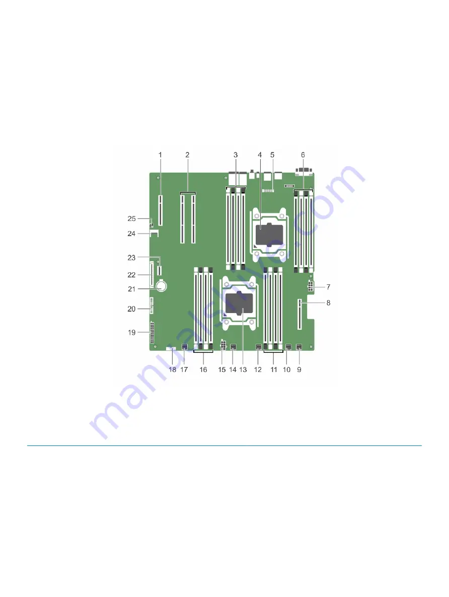
System board connectors
Figure 80. System board connectors and jumpers
Table 38. System board connectors and jumpers
Item
Connector
Description
1
PCIE _G3_X8 (PCH)
PCIE Slot 3 (x4)
2
PCIE_G3_X16 (CPU1)
PCIe Slot 2 and PCIe Slot 1 (PCIe Slot is closer to the CPU2
socket)
3
B1, B5, B2, B6
DIMMS for CPU2 channels 0&1
4
CPU2
Processor socket 2
5
J-AMEA
Remote management port card connector
6
B8, B4, B7, B3
DIMMS for CPU2 channels 2&3
Jumpers and connectors
151


