background image

Enable administrative communication

For HA pairs, administrative communication must be enabled on both nodes.

The administrative interfaces are located on the management module on the rear of
the chassis. These interfaces are for management network traffic only. Do not use
these interfaces for data traffic.

1. Connect an administrative console to the serial port on the back panel of the

system.

2.

Note

You must have 115200 baud rate for the system to work correctly; 9600 baud rate
does not work.

Launch a terminal emulation program from your computer and configure the
following communication settings:

Table 48 Communications settings

Setting

Value

Baud rate

115200

Data bits

8

Stop bits

1

Parity

None

Flow control

None

Emulation

VT-100

3. Press 

Enter

 to activate the console.

Note

If you do not see the prompt on your terminal to log in, then complete Step 4.

4. Verify the front blue power LED (blue square) is on. If it is not, make sure the

power cables are fully seated at both ends, and both AC sources are on.

5.

Note

The initial username is 

sysadmin

 and the initial password is the system serial

number.

Log in to the Data Domain console using the 

sysadmin

 username.

localhost.localdomain login: 

sysadmin

6. Type the default password, which is the system serial number. The Product ID/SN

tag is attached beneath the power supply at the rear of the system. See the rear
panel of the system for the Product ID/SN tag.

Password: 

system_serial_number

Configure System for Use

74

Data Domain DD6300, DD6800, and DD9300 Systems


6.1 


Hardware Overview and Installation Guide

Summary of Contents for DD6300

Page 1: ...Dell EMC Data Domain DD6300 DD6800 and DD9300 Systems Version 6 1 Hardware Overview and Installation Guide 302 003 008 REV 08 ...

Page 2: ...ATION AND SPECIFICALLY DISCLAIMS IMPLIED WARRANTIES OF MERCHANTABILITY OR FITNESS FOR A PARTICULAR PURPOSE USE COPYING AND DISTRIBUTION OF ANY DELL SOFTWARE DESCRIBED IN THIS PUBLICATION REQUIRES AN APPLICABLE SOFTWARE LICENSE Dell EMC and other trademarks are trademarks of Dell Inc or its subsidiaries Other trademarks may be the property of their respective owners Published in the USA Dell EMC Ho...

Page 3: ...res 28 DD6300 system specifications 29 Internal system components 30 DIMMs overview 30 DD6800 system features 31 DD6800 system specifications 32 Internal system components 33 DIMMs overview 33 DD9300 system features 34 DD9300 system specifications 35 Internal system components 36 DIMMs overview 36 Install the System in the Rack 39 Unpack the system 40 Rails and cable management assembly 40 Identif...

Page 4: ... Cloud Tier 64 DD9300 with DD Cloud Tier or HA and DD Cloud Tier 65 DD6800 and DD9300 with ERSO 67 Connecting the HA interconnect 69 Installing the front bezel 70 Connect data cables 70 Power on all systems 71 Configure System for Use 73 Enable administrative communication 74 Accepting the End User License Agreement EULA 75 Run the configuration wizard 75 Configuring the network 75 Configuring add...

Page 5: ...40 Cable management assembly CMA 41 Warning about lifting the system 43 Service tag components removed for clarity 45 Installing the CMA on the rack 45 Adjusting the CMA depth 46 DD6300 with ES30 shelves 52 DD6800 and DD9300 with ES30s single node DD Cloud Tier or ER 54 DD6800 and DD9300 with ES30s and HA or HA with DD Cloud Tier 56 HA interconnect 70 1 2 3 4 5 6 7 8 9 10 11 12 13 14 15 16 17 18 1...

Page 6: ...FIGURES 6 Data Domain DD6300 DD6800 and DD9300 Systems 6 1 Hardware Overview and Installation Guide ...

Page 7: ...ions 32 System operating environment 32 DD6800 memory DIMM configuration 33 Memory locations CPU 0 33 Memory locations CPU 1 34 DD9300 system features 34 DD9300 system specifications 35 System operating environment 35 DD9300 memory DIMM configuration 36 Memory locations CPU 0 36 Memory locations CPU 1 37 Cables for primary node to ES30 shelf loop 50 Cables for standby node to ES30 shelf loop 50 ES...

Page 8: ...TABLES 8 Data Domain DD6300 DD6800 and DD9300 Systems 6 1 Hardware Overview and Installation Guide ...

Page 9: ...6 1 Added rack dimensions corrected power specifications and editorial revisions 06 June 2017 302 003 008 6 1 Editorial revisions 05 April 2017 302 003 008 6 0 Editorial revisions 04 January 2017 302 003 008 6 0 Added heat dissipation BTU hr to the system specifications 03 December 2016 302 003 008 6 0 Editorial revisions 02 October 2016 302 003 008 6 0 Editorial revisions 01 October 2016 302 003 ...

Page 10: ...Revision history 10 Data Domain DD6300 DD6800 and DD9300 Systems 6 1 Hardware Overview and Installation Guide ...
Page 11: ...CHAPTER 1 Planning and Site Preparation l Tools and supplies needed 12 l Safety information 12 l Field installed systems vs factory racked systems 13 Planning and Site Preparation 11 ...

Page 12: ...h memory drive l Tie wraps 4 in and 8 in l recommended Roll of 5 8 inch Velcro cable tie material 3M Scotchmate SJ 3401 or similar Safety information CAUTION l If the system is used in a manner that is not specified by the manufacturer the protection that is provided by the equipment may be impaired l The RJ45 sockets on the motherboard PCI cards or I O modules are for Ethernet connection only and...

Page 13: ... expansion shelf weighs up to 68 lbs 30 8 kg A DS60 shelf weighs up to 225 lbs 102 KG CAUTION Data Domain systems are heavy Use at least two people or a mechanical lift to move any system l Do not lift an expansion shelf by the front handles on any modules The handles are not designed to support the weight of the populated shelf l To comply with applicable safety emission and thermal requirements ...

Page 14: ...es already connected Follow the instructions in the chapter Configure System For Use to configure the factory racked system The following documents available from the Online Support website at https support emc com provide additional information about the factory rack l Dell EMC 40U P Cabinet Site Preparation Guide l Dell EMC 40U P Cabinet Unpacking and Setup Guide l Data Domain Rack Service Guide...

Page 15: ...system features 28 l DD6300 system specifications 29 l Internal system components 30 l DD6800 system features 31 l DD6800 system specifications 32 l Internal system components 33 l DD9300 system features 34 l DD9300 system specifications 35 l Internal system components 36 Data Domain DD6300 DD6800 and DD9300 Hardware Overview 15 ...

Page 16: ...s Usable internal capacity DD6300 base configuration Seven 4 TB HDDs 14 TB DD6300 expanded configuration factory Twelve 4 TB HDDs 34 TB DD6300 expanded configuration upgrade Seven 4 TB HDDs Five 4 TB HDDs 22 TB Table 3 DD6300 AIO configuration Slot 0 HDD 1 Slot 1 HDD 2 Slot 2 HDD 3 Slot 3 HDD 4 Slot 4 HDD 5 Slot 5 HDD 6 Slot 6 HDD 7 Slot 7 Filler Slot 8 Filler Slot 9 Filler Slot 10 Filler Slot 11 ...

Page 17: ...Slot 10 Filler Slot 11 Filler DD9300 front panel DD9300 Dataless Head DLH systems have one of the following front panel drive configurations to host the DD OS boot drives and provide metadata caching on SSD Table 8 DD9300 DLH SSD requirements Configuration Number of SSDs DD9300 5 DD9300 expanded 8 Note SSDs are not RAID protected Table 9 DD9300 DLH configuration drive layout Slot 0 HDD 1 Slot 1 HD...

Page 18: ... power LED is present that is on whenever the system has power An amber system fault LED is also present that is normally off and lit amber whenever the chassis or any other FRU in the system requires service Figure 2 Front LED indicators 1 System service LED 2 Drive activity service LED 3 System power LED Table 11 Front LEDs Name Color Purpose System power LED Blue Indication that the system has ...

Page 19: ...module DD6300 rear SSDs The D6300 system uses one or two 800 GB SSDs mounted at the rear of the chassis for metadata caching Configuration Number of SSDs SSD location DD6300 1 SSD slot 0 DD6300 expanded 2 SSD slots 0 and 1 Note SSDs are not RAID protected Rear LED indicators Figure 3 Rear LED indicators 1 Do not remove LED 2 SP service LED 3 System power LED 4 AC power good LED 5 DC power good LED...

Page 20: ...OS 4 Hz Drive Power Activity LED a Left LED on the SSD Blue Lit blue when the drive is powered Blinks during drive activity Drive Fault LED a Right LED on the SSD Amber Lit solid amber when a drive needs service System power LED Right most LED on the management panel Blue SP has good stable power PSU FRU LED AC Good Top LED on power supply Green AC input is as expected PSU FRU LED DC Good Middle L...

Page 21: ... is functioning normally l Amber I O module has encountered a fault condition and requires service I O port status LED SAS Fibre Channel and optical networking I O modules only One LED per I O module port Blue Lit when port is enabled May flash if SW marks the port a a For RJ45 networking ports the standard green link and amber activity LEDs are used Data Domain DD6300 DD6800 and DD9300 Hardware O...

Page 22: ...k Onboard network port LED Activity LED Bottom LED on network port Amber Blinks when there is traffic on the port I O modules I O module slot numbering The eight I O module slots are enumerated as Slot 0 on the left when viewed from the rear through Slot 7 Ports on an I O module are enumerated as 0 through 3 with 0 being on the bottom Figure 6 I O module slot numbering 1 Slot 0 2 Slot 1 3 Slot 2 4...

Page 23: ... Port 16 Gbps Fibre Channel Optional Quad Port 10GbE SR Quad Port 10 GBase T or Dual Port 16 Gbps Fibre Channel Optional Quad Port 6 Gbps SAS a AIO NVRAM 8g Model 3 Quad Port 10 GBase T Reserved Quad Port 10GbE SR Quad Port 10 GBase T or Dual Port 16 Gbps Fibre Channel Quad Port 10GbE SR Quad Port 10 GBase T or Dual Port 16 Gbps Fibre Channel Quad Port 10GbE SR Quad Port 10 GBase T or Dual Port 16...

Page 24: ...e Quad Port 10 GBase T I O modules are supported in slots 3 6 because of the mandatory Quad Port 10 GBase T I O module in slot 1 The following table assigns rules for populating the I O modules Table 14 I O module slot population rules Step I O module name Slots Notes Step 1 Populate mandatory I O modules NVRAM 8g Model 3 0 Mandatory for all configurations Quad Port 10 GBase T 1 Mandatory for all ...

Page 25: ...e T in slot 1 max number of Quad Port 10 GBase T I O modules are limited to 4 Step 4 Populate all Dual Port 16 Gbps Fibre Channel I O modules Dual Port 16 Gbps Fibre Channel 6 5 4 3 Populate starting from the highest available slot number Data Domain DD6300 DD6800 and DD9300 Hardware Overview I O modules 25 ...

Page 26: ... 7 5 internal drives 22 TB l 12 internal drives 34 TB l External 48 TB l 7 internal drives 12 74 TiB l 7 5 internal drives 20 02 TiB l 12 internal drives 30 94 TiB l External 43 68 TiB l 7 internal drives 14 000 GB l 7 5 internal drives 22 000 GB l 12 internal drives 34 000 GB l External 48 000 GB l 7 internal drives 13 039 GiB l 7 5 internal drives 20 489 GiB l 12 internal drives 31 665 GiB l Ext...

Page 27: ... GiB l Cloud Tier 536 442 GiB l Cloud Tier metadata 89 407 GiB a The capacity differs depending on the size of the external storage shelves used This data based on ES30 shelves b HA is supported c HA is not supported with Extended Retention d HA is supported in combination with Cloud Tier DD9300 storage capacity The following table provides storage capacity information for the DD9300 system Table ...

Page 28: ...d with Extended Retention d HA is supported in combination with Cloud Tier DD6300 system features Table 18 DD6300 system features Feature DD6300 AIO Base configuration DD6300 AIO Expanded configuration Rack height 2U 2U Processor E5 2620 V3 E5 2620 V3 Kernel 3 2 x 3 2 x Memory configuration Non extended retention 48GB 96GB DIMMs 6x8 GB 12x8 GB Supported capacity Non extended retention 76 TB 28 TB ...

Page 29: ... consumption 25 C Heat dissipation operating maximum Weight a Width Depth Height DD6300 530W 1 69 x 106 J hr 1604 Btu hr maximum 80 lbs 36 29 kg 17 50 in 44 45 cm 30 5 in 77 5 cm 3 40 in 8 64 cm a The weight does not include mounting rails Allow 2 3 4 5 kg 5 10 lb for a rail set Table 20 System operating environment Requirement Description Ambient temperature 10 C 35 C derate 1 1 C per 1 000 ft 30...

Page 30: ...s a total of 16 DIMM slots DD6300 memory DIMM configuration Table 21 DD6300 memory DIMM configuration Tier Total Memory Memory DIMM Configuration DD6300 AIO Expanded 96 GB 12 x 8 GB DD6300 AIO 48 GB 6 x 8 GB To ensure maximum memory performance there are memory DIMM population rules for best memory loading and interleaving Table 22 on page 30 and Table 23 on page 31 specify the DIMM location rules...

Page 31: ... 192 GB a DIMMs 8x8 GB 8x16 GB 8x8 GB 8x16 GB Supported capacity Non extended retention Active tier 144 TB 288 TB DD Cloud Tier N A 576 TB b Extended retention Archive tier N A 288 TBa Stream count 405 writes 112 reads 405 writes 112 reads HDDs in 3 5 bays 4 4 SSDs in 3 5 bays 2 4 SSDs in 2 5 bays 0 0 NVRAM NVRAM 8g Model 3 NVRAM 8g Model 3 High availability configuration support Yes Yes HA Privat...

Page 32: ...onsumption 25 C Heat dissipation operating maximum Weight a Width Depth Height DD6800 560W 1 69 x 106 J hr 1604 Btu hr maximum 68 lbs 30 84 kg 17 50 in 44 45 cm 30 5 in 77 5 cm 3 40 in 8 64 cm a The weight does not include mounting rails Allow 2 3 4 5 kg 5 10 lb for a rail set Table 26 System operating environment Requirement Description Ambient temperature 10 C 35 C derate 1 1 C per 1 000 ft 304 ...

Page 33: ...D6800 memory DIMM configuration Table 27 DD6800 memory DIMM configuration Tier Total Memory Memory DIMM Configuration DD6800 DLH 192 GB 8 x 16 GB 8 x 8 GB DD6800 DLH Extended Retention DD Cloud Tier 192 GB 8 x 16 GB 8 x 8 GB HA is supported with all available memory configurations To ensure maximum memory performance there are memory DIMM population rules for best memory loading and interleaving T...

Page 34: ...r E5 2680 V3 E5 2680 V3 Kernel 3 2 x 3 2 x Memory con figuration Non extended retention 192 GB 384 GB DD Cloud Tier N A 384 GB Extended retention N A 384 GB a DIMMs 4x32 GB 4x16 GB 8x32 GB 8x16 GB Supported capacity Non extended retention Active tier 384TB 720 TB DD Cloud Tier N A 1440 TB b Extended retention Archive tier N A 720 TB a Stream count 810 writes 225 reads 810 writes 225 reads HDDs in ...

Page 35: ...0 shelves fully populated with 4 TB drives to store DD Cloud Tier metadata DD9300 system specifications Table 31 DD9300 system specifications Model Average power consumption 25 C Heat dissipation operating maximum Weight a Width Depth Height DD9300 645W 1 69 x 106 J hr 1604 Btu hr maximum 70 lbs 31 75 kg 17 50 in 44 45 cm 30 5 in 77 5 cm 3 40 in 8 64 cm a The weight does not include mounting rails...

Page 36: ...tion Table 33 DD9300 memory DIMM configuration Tier Total Memory Memory DIMM Configuration DD9300 DLH Expanded 384 GB 8 x 32 GB 8 x 16 GB DD9300 DLH 192 GB 4 x 32 GB 4 x 16 GB DD9300 DLH Extended Retention DD Cloud Tier 384 GB 8 x 32 GB 8 x 16 GB HA is supported with all available memory configurations To ensure maximum memory performance there are memory DIMM population rules for best memory load...

Page 37: ... Memory locations CPU 1 Channel A Channel B Channel D Channel C Tier Total Memory 8 9 10 11 12 13 14 15 DD9300 DLH Expanded 384 GB 32 GB 16 GB 32 GB 16 GB 16 GB 32 GB 16 GB 32 GB DD9300 DLH 192 GB 32 GB N A 32 GB N A N A 16 GB N A 16 GB DD9300 DLH Extended Retention DD Cloud Tier 384 GB 32 GB 16 GB 32 GB 16 GB 16 GB 32 GB 16 GB 32 GB Data Domain DD6300 DD6800 and DD9300 Hardware Overview DIMMs ove...

Page 38: ...Data Domain DD6300 DD6800 and DD9300 Hardware Overview 38 Data Domain DD6300 DD6800 and DD9300 Systems 6 1 Hardware Overview and Installation Guide ...

Page 39: ...ment assembly 40 l Identify the rack location to install the system 41 l Install the rails 41 l Install the DD6300 DD6800 or DD9300 system into a rack 43 l Installing the cable management assembly CMA 45 l Installing the expansion shelves into the racks 46 Install the System in the Rack 39 ...

Page 40: ...p fits square and round hole unthreaded racks Large flat headed M4 screws insert through the rail into the rail kit to secure the rail to the rack When installing rails do not tighten the screws all the way until all the screws are in place This assures that the screws are all screwed in the same distance and prevents one from skewing the others The rail kit includes two bracket assemblies one mar...

Page 41: ...gle node or the primary node of an HA pair is U22 U23 in rack 1 n The designated location for the standby node of an HA pair is U25 26 in rack 1 Note The designated slots in the rack are the recommended location for the DD6300 DD6800 and DD9300 systems to support the cabling described in this document Other locations may require different cable lengths for some configurations Install the rails Thi...

Page 42: ... front of the rails in place Do not fully tighten the screw at this time Note An 18 inch screwdriver minimum is required to install the screw into the rear of the rails 4 At the rear of the cabinet align and insert the two adaptors on the rear of the rail with the mounting holes in the NEMA channel Make sure the rail is level Install the System in the Rack 42 Data Domain DD6300 DD6800 and DD9300 S...

Page 43: ...led in the pre defined location for the system controller in the rack to comply with Data Domain rack mounting guidelines l Do not apply AC power to the system controller until all expansion shelves and cables are installed l Ensure the PSNT label which is in a slot just beneath the power supply on the rear of the chassis is not damaged or snagged during the installation of the system into the rac...

Page 44: ...th the NEMA channel 3 Secure the unit to the NEMA channel and rails using four screws two on each side 4 Check the PSNT label in the slot just beneath the power supply at the rear of the chassis Install the System in the Rack 44 Data Domain DD6300 DD6800 and DD9300 Systems 6 1 Hardware Overview and Installation Guide ...

Page 45: ... and organized Procedure 1 Align and insert the CMA tabs in the tongues on the rails and align the plunger in the hole of the mounting rail on both sides 2 Working one side at a time pull out the plunger and slide the CMA tabs as required until the plunger pin snaps into the mounting hole of the rail Figure 14 Installing the CMA on the rack Install the System in the Rack Installing the cable manag...

Page 46: ... CMA in place Adjust the depth of the CMA arms to access these modules Figure 15 Adjusting the CMA depth Installing the expansion shelves into the racks CAUTION l Data Domain systems are heavy Always use two people or a mechanical lift to move and install a Data Domain system Use caution to install the expansion shelves l Ensure that each rack is securely anchored to prevent tipping 1 From the fro...

Page 47: ... for Data Domain metadata on flash l The SSD shelf counts towards the total number of shelves connected to the system l Data Domain recommends installing the SSD shelf in the V1 1 positon but if that is not possible the shelf can be placed in a different location in the rack so long as cables of sufficient length are available Note V1 1 is recommended for better performance because this will the 1...

Page 48: ...Install the System in the Rack 48 Data Domain DD6300 DD6800 and DD9300 Systems 6 1 Hardware Overview and Installation Guide ...
Page 49: ...es and Power on l Connecting ES30 shelves 50 l Connecting DS60 shelves 57 l Connecting the HA interconnect 69 l Installing the front bezel 70 l Connect data cables 70 l Power on all systems 71 Connect Cables and Power on 49 ...

Page 50: ...dby nodes use different cables to connect to ES30 shelves The primary node uses cables for ES30 host ports and the standby node uses cables for ES30 expansion ports ES30 cable information When connecting ES30 shelves different cables are required for the following connections l Connecting the primary node to the ES30 shelf loop l Connecting the standby node to the ES30 shelf loop l Connecting an E...

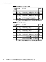
Page 51: ... the following list and connect the disk shelves to the Data Domain controller l DD6300 on page 51 l DD6800 and DD9300 single node DD Cloud Tier or ERSO on page 52 l DD6800 and DD9300 HA or HA with DD Cloud Tier on page 54 DD6300 The DD6300 system supports a maximum of four shelves cabled in a single set String Loop I O Port Shelf Port Length a 1 I O 7 Port 0 B controller HOST port of shelf V1 1 2...

Page 52: ...0 and DD9300 systems support a maximum of 28 shelves divided into four sets of seven shelves Note For configurations of 16 SAS shelves or less do not exceed four shelves per set Connect Cables and Power on 52 Data Domain DD6300 DD6800 and DD9300 Systems 6 1 Hardware Overview and Installation Guide ...

Page 53: ...the highest number shelf in V2 2M 3 I O 7 Port 1 B controller HOST port of shelf V3 1 2M 3 I O 2 Port 1 A controller HOST port of the highest number shelf in V3 2M 4 I O 7 Port 3 B controller HOST port of shelf V4 1 3M 4 I O 2 Port 3 A controller HOST port of the highest number shelf in V4 3M a Cable lengths shown are designed for Data Domain racks Longer cables up to 5M can be used Connect Cables...

Page 54: ... Tier The DD6800 and DD9300 systems support a maximum of 28 shelves divided into four sets of seven shelves Note For configurations of 16 SAS shelves or less do not exceed four shelves per set Connect Cables and Power on 54 Data Domain DD6300 DD6800 and DD9300 Systems 6 1 Hardware Overview and Installation Guide ...
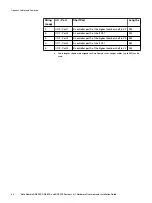
Page 55: ...n racks Longer cables up to 5M can be used Table 40 Standby node cabling instructions String Loop I O Port Shelf Port Length a 1 I O 7 Port 0 A controller EXPANSION port of shelf V1 1 2M 1 I O 2 Port 0 B controller EXPANSION port of the highest number shelf in V1 2M 2 I O 7 Port 2 A controller EXPANSION port of shelf V2 1 2M 2 I O 2 Port 2 B controller EXPANSION port of the highest number shelf in...

Page 56: ...Figure 18 DD6800 and DD9300 with ES30s and HA or HA with DD Cloud Tier Connect Cables and Power on 56 Data Domain DD6300 DD6800 and DD9300 Systems 6 1 Hardware Overview and Installation Guide ...

Page 57: ...f the SSD shelf is connected to the last enclosure in a chain then each read write request has to go through many hops which introduces latency issues when compared to when the SSD shelf is on the 1st shelf of a chain 5 Use the cable management assembly to support and organize all cables DS30 cable information When connecting DS60 shelves the same cable type connects a controller to a DS60 shelf o...

Page 58: ...t 0 of the DS60 2M 1 I O 7 Port 1 B controller port 0 of the DS60 2M a Cable lengths shown are designed for Data Domain racks Longer cables up to 5M can be used Connect Cables and Power on 58 Data Domain DD6300 DD6800 and DD9300 Systems 6 1 Hardware Overview and Installation Guide ...

Page 59: ...elf Port Length a 1 I O 7 Port 0 A controller port 0 of shelf V1 1 2M 1 I O 2 Port 0 B controller port 0 of the highest number shelf in V1 2M 2 I O 7 Port 1 A controller port 0 of shelf V2 1 2M Connect Cables and Power on DD6800 and DD9300 59 ...

Page 60: ...t 2 A controller port 0 of shelf V3 1 2M 3 I O 2 Port 2 B controller port 0 of the highest number shelf in V3 2M a Cable lengths shown are designed for Data Domain racks Longer cables up to 5M can be used Connect Cables and Power on 60 Data Domain DD6300 DD6800 and DD9300 Systems 6 1 Hardware Overview and Installation Guide ...
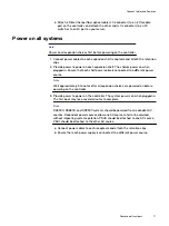
Page 61: ...M a Cable lengths shown are designed for Data Domain racks Longer cables up to 5M can be used Table 43 Standby node cabling instructions String Loop I O Port Shelf Port Length a 1 I O 7 Port 0 B controller port 2 of shelf V1 1 2M 1 I O 2 Port 0 A controller port 2 of the highest number shelf in V1 2M 2 I O 7 Port 1 B controller port 2 of shelf V2 1 2M 2 I O 2 Port 1 A controller port 2 of the high...

Page 62: ...rt Length a 1 I O 7 Port 0 A controller port 0 of shelf V1 1 2M 1 I O 2 Port 0 B controller port 0 of the highest number shelf in V1 2M Connect Cables and Power on 62 Data Domain DD6300 DD6800 and DD9300 Systems 6 1 Hardware Overview and Installation Guide ...

Page 63: ...oller HOST port of the second metadata shelf 2M 2 I O 2 Port 1 B controller HOST port of the first metadata shelf 2M a Cable lengths shown are designed for Data Domain racks Longer cables up to 5M can be used Connect Cables and Power on DD6800 with DD Cloud Tier 63 ...

Page 64: ... Domain racks Longer cables up to 5M can be used Table 45 Standby node cabling instructions String Loop I O Port Shelf Port Length a 1 I O 7 Port 0 B controller port 2 of shelf V1 1 2M 1 I O 2 Port 0 A controller port 2 of the highest number shelf in V1 2M 2 I O 7 Port 2 B controller EXPANSION port of the second metadata shelf 2M 2 I O 2 Port 2 A controller EXPANSION port of the first metadata she...

Page 65: ...ode cabling instructions String Loop I O Port Shelf Port Length a 1 I O 7 Port 0 A controller port 0 of shelf V1 1 2M 1 I O 2 Port 0 B controller port 0 of the highest number shelf in V1 2M Connect Cables and Power on DD9300 with DD Cloud Tier or HA and DD Cloud Tier 65 ...

Page 66: ... cabling instructions String Loop I O Port Shelf Port Length a 1 I O 7 Port 0 B controller port 2 of shelf V1 1 2M 1 I O 2 Port 0 A controller port 2 of the highest number shelf in V1 2M 2 I O 7 Port 1 B controller port 2 of shelf V2 1 2M 2 I O 2 Port 1 A controller port 2 of the highest number shelf in V2 2M 3 I O 7 Port 2 B controller port 2 of shelf V3 1 2M 3 I O 2 Port 2 A controller port 2 of...

Page 67: ...elf Port Length a 1 I O 7 Port 0 A controller port 0 of shelf V1 1 2M 1 I O 2 Port 0 B controller port 0 of the highest number shelf in V1 2M 2 I O 7 Port 1 A controller port 0 of shelf V2 1 2M Connect Cables and Power on DD6800 and DD9300 with ERSO 67 ...

Page 68: ...roller port 0 of the highest number shelf in V3 5M 4 I O 7 Port 3 A controller port 0 of shelf V4 1 5M 4 I O 2 Port 3 B controller port 0 of the highest number shelf in V4 5M a Cable lengths shown are designed for Data Domain racks Longer cables up to 5M can be used Connect Cables and Power on 68 Data Domain DD6300 DD6800 and DD9300 Systems 6 1 Hardware Overview and Installation Guide ...

Page 69: ...ode in the HA pair This connection between the two nodes provides the standby node with the information needed to fail over if the active node suffers a failure and maintain the connections to hosts and clients after the failover is complete Connect Cables and Power on Connecting the HA interconnect 69 ...

Page 70: ...ently push the bezel into place on the cabinet until it latches 3 If the bezel has a key lock lock the bezel the provided key Connect data cables 1 Enable data transfer Ethernet connectivity Repeat for each connection a If using 1 Gb copper Ethernet attach a Cat 5e or Cat 6 copper Ethernet cable to an RJ 45 Ethernet network port start with ethMa and go up b If using 10 Gb copper Ethernet with an S...

Page 71: ...wer source Note Wait approximately 3 minutes after all expansion shelves are powered on before powering on the controller 3 Provide power to power on the controller The system powers on when plugged in The first boot may take several minutes to complete Note DD6300 DD6800 and DD9300 systems should be powered from redundant AC sources Redundant power sources allow one AC source to fail or be servic...

Page 72: ...Connect Cables and Power on 72 Data Domain DD6300 DD6800 and DD9300 Systems 6 1 Hardware Overview and Installation Guide ...

Page 73: ...APTER 5 Configure System for Use l Enable administrative communication 74 l Accepting the End User License Agreement EULA 75 l Run the configuration wizard 75 l Configure HA 78 Configure System for Use 73 ...

Page 74: ... Stop bits 1 Parity None Flow control None Emulation VT 100 3 Press Enter to activate the console Note If you do not see the prompt on your terminal to log in then complete Step 4 4 Verify the front blue power LED blue square is on If it is not make sure the power cables are fully seated at both ends and both AC sources are on 5 Note The initial username is sysadmin and the initial password is the...

Page 75: ...it from the EULA acceptance screen and continue the installation The customer can later type the following to redisplay the EULA and accept it system show eula Run the configuration wizard The CLI configuration wizard starts automatically the first time the system starts The wizard prompts you through a series of questions that provide just enough information for initial system configuration and b...

Page 76: ... routing gateway Or accept the IPv6 address of the default gateway if the system was able to discover it If IPv6 is not in use leave the field empty and press Enter to continue IPV6 Default Gateway Enter the ipv6 default gateway IP address 8 Enter up to three DNS servers to use for resolving host names to IP addresses Use a comma separated or space separated list Enter a space for no DNS servers O...

Page 77: ...up the system location enter config set location Dallas Regional Data Center Lab 5000 Apple Drive Suite 130 Dallas Tx The System Location is Dallas Regional Data Center Lab 5000 Apple Drive Suite 130 Dallas Tx 3 To add one or more time servers enter ntp add timeserver 192 168 101 1 Remote Time Servers 192 168 10 1 4 To enable the NTP daemon enter ntp enable NTP enabled 5 To change the system time ...

Page 78: ...ll serve as the primary node 2 On the primary node create the HA pairing Run the following command ha create peer ipaddr hostname ha name ha system name Note l Specify the hostname or the IP address of the standby node l Specifying an HA system name n Assigns node 0 the local hostname HA system name p0 n Assigns node 1 the local hostname HA system name p1 l The ha create command will fail if one n...

Page 79: ...on is the only way to configure a floating IP address There is no method available in Data Domain System Manager to configure a floating IP address net config eth1a 2 2 2 1 netmask 255 255 255 0 type floating Configure System for Use Configure HA 79 ...

Page 80: ...Configure System for Use 80 Data Domain DD6300 DD6800 and DD9300 Systems 6 1 Hardware Overview and Installation Guide ...

Reviews: