Steps
1. Align and place the power-supply unit into the slot on the chassis.
2. Slide the power-supply unit into the slot until it clicks in place.
3. Replace the three screws (M6X32) to secure the power-supply unit to the chassis.
4. Route the power-supply cables through routing guides and connect it to the connectors on the system board.
5. Place the support bracket into the slot and secure it with the two screws (M6X32).
6. Connect the optical-drive SATA cable through the retention clip on the support bracket.
Next steps
1. Install the
.
2. Install the
hard-drive and optical-drive bracket
3. Install the
.
after working inside your computer
.
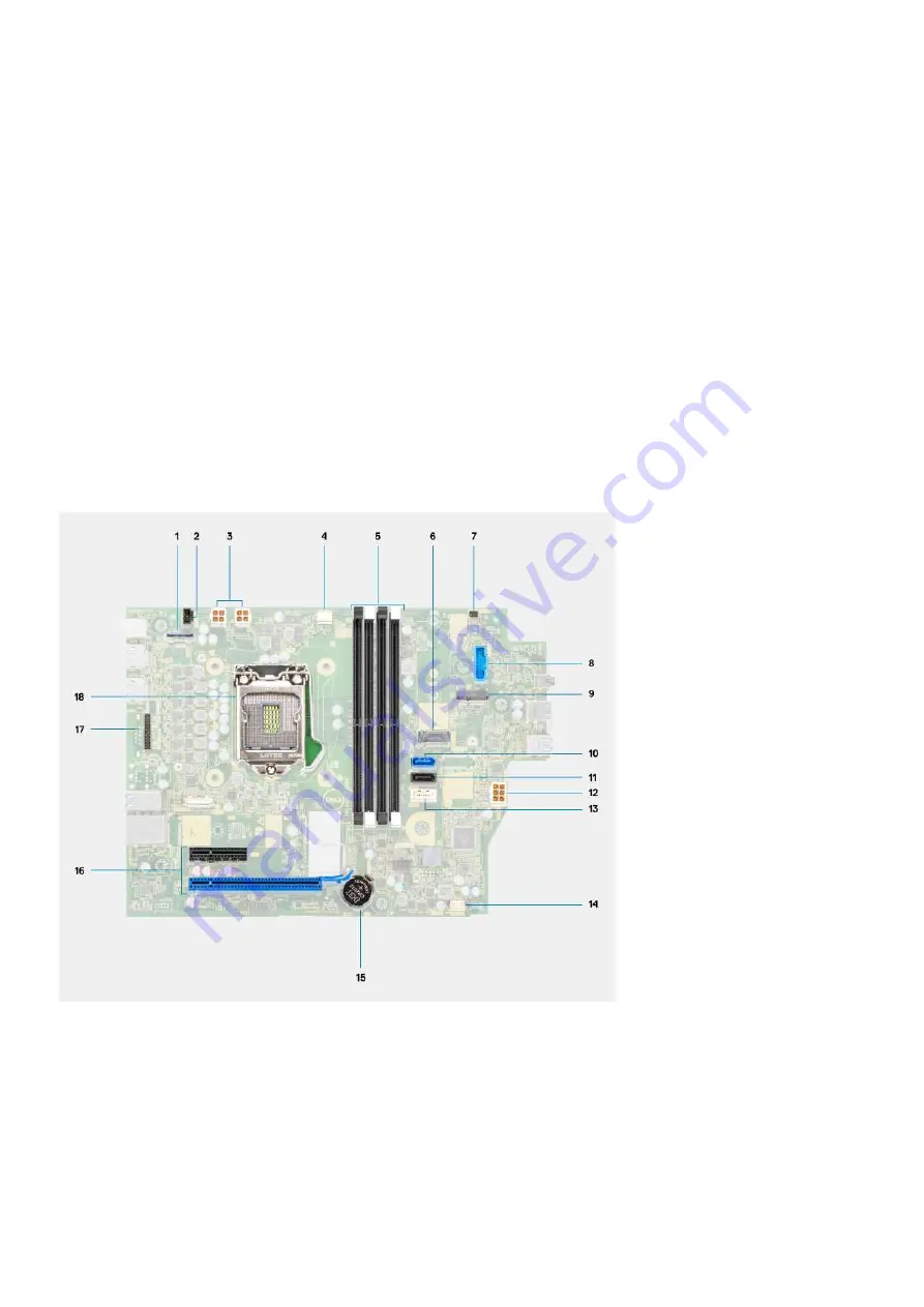
System board
System board callouts - 5090 Small Form Factor
1. Video connector
2. Intrusion switch connector
3. ATX CPU power connector
4. Processor fan connector
5. Memory module connector
6. M.2 SSD PCIe connector
7. Power button connector
8. SD-card reader connector
9. M.2 WLAN connector
Removing and installing components
55
Summary of Contents for D15S
Page 11: ...Major components of your system 1 Side cover Removing and installing components 11 ...
Page 18: ...18 Removing and installing components ...
Page 28: ...28 Removing and installing components ...
Page 30: ...30 Removing and installing components ...
Page 51: ...Removing and installing components 51 ...
Page 53: ...Removing and installing components 53 ...
Page 54: ...54 Removing and installing components ...
Page 57: ...Removing and installing components 57 ...
Page 58: ...58 Removing and installing components ...
Page 60: ...60 Removing and installing components ...


