background image

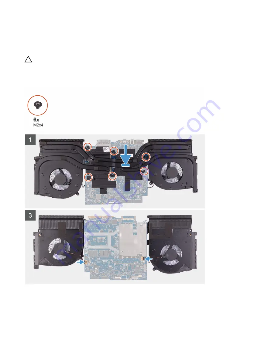
Installing the fan and heat-sink assembly

Prerequisite
If you are replacing a component, remove the existing component before performing the installation procedure.

CAUTION: If either the processor or the heat sink is replaced, use the thermal grease provided in the kit to ensure 

that thermal conductivity is achieved.

About this task
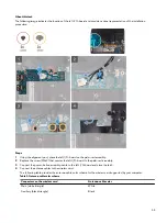
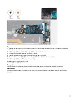
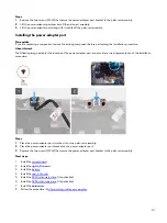
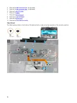
The following image indicates the location of the fan and heat-sink assembly and provides a visual representation of the 
installation procedure.

Steps

Place the fan and heat-sink assembly on the system board.

2  In sequential order (1>2>3>4>5>6) replace the six screws (M2x3) that secure the fan and heat-sink assembly to the 

system board.

3  Connect the left and right fan cables to the system board.

47

Summary of Contents for Alienware m15 R2

Page 1: ...Alienware m15 R2 Service Manual Regulatory Model P87F Regulatory Type P87F001 ...

Page 2: ...ive 13 Removing the M 2 2230 solid state drive 13 Installing the M 2 2230 solid state drive 14 Removing the M 2 2280 solid state drive 16 Installing the M 2 2280 solid state drive 17 Rear I O cover 18 Removing the rear I O cover 18 Installing the rear I O cover 19 Display assembly 20 Removing the display assembly 21 Installing the display assembly 23 Battery 25 Removing the battery 25 Installing t...

Page 3: ...t 50 Installing the power adapter port 51 Power button assembly 52 Removing the power button assembly 52 Installing the power button assembly 52 Keyboard 53 Removing the keyboard 53 Installing the keyboard 55 Palm rest 58 Removing the palm rest 58 Installing the palm rest 59 Device drivers 60 Intel Chipset Software Installation Utility 60 Video drivers 60 Intel Serial IO driver 60 Intel Trusted Ex...

Page 4: ...cs 67 Running the ePSA diagnostics 67 System diagnostic lights 67 Flashing BIOS USB key 68 Flashing the BIOS 68 Backup media and recovery options 69 WiFi power cycle 69 Flea power release 69 Getting help and contacting Dell 70 Self help resources 70 Contacting Dell 70 4 ...

Page 5: ...engage before disconnecting the cable When disconnecting cables keep them evenly aligned to avoid bending any connector pins When connecting cables ensure that the ports and connectors are correctly oriented and aligned CAUTION Press and eject any installed card from the media card reader Before working inside your computer NOTE The images in this document may differ from your computer depending o...

Page 6: ...side a bag Wrist Strap and Bonding Wire The wrist strap and bonding wire can be either directly connected between your wrist and bare metal on the hardware if the ESD mat is not required or connected to the anti static mat to protect hardware that is temporarily placed on the mat The physical connection of the wrist strap and bonding wire between your skin the ESD mat and the hardware is known as ...

Page 7: ...arts in anti static bags for safe transport Lifting equipment Adhere to the following guidelines when lifting heavy weight equipment CAUTION Do not lift greater than 50 pounds Always obtain additional resources or use a mechanical lifting device 1 Get a firm balanced footing Keep your feet apart for a stable base and point your toes out 2 Tighten stomach muscles Abdominal muscles support your spin...

Page 8: ...en replacing a component NOTE Screw color may vary with the configuration ordered Table 1 Screw list Component Secured to Screw type Quantity Screw image Base cover Palm rest assembly M2 5x5 2 M 2 connector shield System board M2x4 5 1 M 2 2230 solid state drive M 2 2230 mounting bracket M2x3 1 per M 2 2230 solid state drive M 2 2230 mounting bracket Palm rest assembly M2x3 1 per M 2 2230 solid st...

Page 9: ...e support bracket Palm rest assembly M2x1 9 2 Touchpad Palm rest assembly M2x1 9 4 Solid state drive support bracket Palm rest assembly M2x1 9 2 Power adapter port bracket Palm rest assembly M2x3 2 Power button assembly Palm rest assembly M2x1 9 3 Keyboard bracket Palm rest assembly Keyboard M1 2x2 1 9 Keyboard Palm rest assembly M1 2x1 6 33 Base cover Removing the base cover Prerequisite 1 Follow...

Page 10: ...10 ...

Page 11: ...cover off the palm rest assembly 5 Disconnect the battery from the system board 6 Press and hold the power button for 5 seconds to ground the computer and drain the flea power Installing the base cover Prerequisite If you are replacing a component remove the existing component before performing the installation procedure About this task The following image indicates the location of the base cover ...

Page 12: ...Steps 1 Connect the battery cable to the system board 12 ...

Page 13: ...id state drive Prerequisite 1 Follow the procedure in Before working inside your computer 2 Remove the base cover About this task NOTE This procedure applies only to computers shipped with a M 2 2230 solid state drive installed NOTE Depending on the configuration ordered your computer may have up to two M 2 cards installed Supported card configurations per M 2 card slot M 2 2230 solid state drive ...

Page 14: ... the system board 4 Remove the screw M2x3 that secures the M 2 2230 mounting bracket to the palm rest assembly 5 Remove the M 2 2230 mounting bracket from the palm rest assembly Installing the M 2 2230 solid state drive Prerequisite If you are replacing a component remove the existing component before performing the installation procedure About this task NOTE This procedure applies if you are inst...

Page 15: ...ns are ordered If these configurations are installed After Point of Sale APOS contact Dell support for the thermal shield NOTE Before replacing the M 2 card take note that there are two M 2 card slots present on your computer for the left card slot PCIe NVMe and SATA AHCI cards are supported the right card slot only PCIe NVMe cards are supported The following image indicates the location of the M ...

Page 16: ...applies only to computers shipped with a M 2 2280 solid state drive installed NOTE Depending on the configuration ordered your computer may have up to two M 2 cards installed Supported card configurations per M 2 card slot M 2 2230 solid state drive 2230 mounting bracket M 2 2280 solid state drive NOTE For PCIe NVMe solid state drives a thermal shield is required for optimal heat dissipation and i...

Page 17: ...pported card configurations per M 2 card slot M 2 2230 solid state drive 2230 mounting bracket M 2 2280 solid state drive NOTE For PCIe NVMe solid state drives a thermal shield is required for optimal heat dissipation and is installed in your computer when these configurations are ordered If these configurations are installed After Point of Sale APOS contact Dell support for the thermal shield NOT...

Page 18: ...e screw M2x3 that secures the M 2 2280 solid state drive to the palm rest assembly Next step 1 Install the base cover 2 Follow the procedure in After working inside your computer Rear I O cover Removing the rear I O cover Prerequisite 1 Follow the procedure in Before working inside your computer 2 Remove the base cover About this task The following image indicates the location of the rear I O cove...

Page 19: ...cover to the palm rest assembly 4 Firmly grasp the sides of your computer with both hands and push the rubber feet on the rear I O cover outwards with your thumbs to release the rear I O cover from the palm rest assembly 5 Lift the rear I O cover from the palm rest assembly Installing the rear I O cover Prerequisite If you are replacing a component remove the existing component before performing t...

Page 20: ...e two screws M2 5x5 that secure the rear I O cover to the palm rest assembly 3 Peel and lift the Mylar from the system board 4 Route the Tron light cable through the slot on the Mylar 5 Connect the Tron light cable to the system board 6 Route and adhere the Tron light cable into place on the system board 7 Adhere the Mylar into place onto the system board Next steps 1 Install the base cover 2 Foll...

Page 21: ... O cover About this task NOTE The display assembly is a Hinge up Display HUD and cannot be further disassembled If components within the display assembly need to be replaced the entire display assembly is to be replaced The following image indicates the location of the display assembly and provides a visual representation of the removal procedure 21 ...

Page 22: ...tenna cables to system board and left fan 6 Remove the antenna cables from the routing guides on the left fan and system board 7 Lift the latch and disconnect the display cable from the connector on the system board 8 Disconnect the G sensor cable from the connector on the system board 9 Disconnect the Tobii eye tracker cable from the connector on the system board NOTE This step is only applicable...

Page 23: ... Installing the display assembly Prerequisite If you are replacing a component remove the existing component before performing the installation procedure About this task NOTE The display assembly is a Hinge up Display HUD and cannot be further disassembled If components within the display assembly need to be replaced the entire display assembly is to be replaced The following image indicates the l...

Page 24: ...y to the palm rest assembly 4 Route the following cables to the routing guides on the palm rest assembly Display cable G sensor cable Tobii eye tracker cable Antenna cables 5 Place the computer face down 6 Connect the Tobii eye tracker cable to the connector on the system board NOTE This step is only applicable to computers shipped with a Tobii eye tracker 7 Connect the G sensor cable to the conne...

Page 25: ...ace the wireless card bracket on the wireless card 13 Replace the screw M2x3 that secures the wireless card bracket to the left I O board 14 Adhere the Mylar over the system board Next steps 1 Install the rear I O cover 2 Install the base cover 3 Follow the procedure in After working inside your computer Battery Removing the battery Prerequisites 1 Follow the procedure in Before working inside you...

Page 26: ...rest assembly 3 Remove the battery from the palm rest assembly Installing the battery Prerequisite If you are replacing a component remove the existing component before performing the installation procedure About this task The following image indicates the location of the battery and provides a visual representation of the installation procedure 26 ...

Page 27: ...battery Prerequisites CAUTION Removing the coin cell battery resets the BIOS setup program s settings to default It is recommended that you note the BIOS setup program s settings before removing the coin cell battery 1 Follow the procedure in Before working inside your computer 2 Remove the base cover 3 Remove the 2230 solid state drive if applicable 4 Remove the 2280 solid state drive if applicab...

Page 28: ... off the palm rest assembly along with its cable 4 Disconnect the coin cell battery from the coin cell battery cable Installing the coin cell battery Prerequisite If you are replacing a component remove the existing component before performing the installation procedure About this task The following image indicates the location of the coin cell battery and provides a visual representation of the i...

Page 29: ...battery cable to the right I O board and palm rest assembly 4 Connect the coin cell battery cable to the connector on the system board Next steps 1 Install the battery 2 Install the 2230 solid state drive if applicable 3 Install the 2280 solid state drive if applicable 4 Install the base cover 5 Follow the procedure in After working inside your computer Keyboard controller board 29 ...

Page 30: ...acklight cable from the keyboard controller board 3 Open the latch and disconnect the keyboard controller board cable from the keyboard controller board 4 Open the latch and disconnect the keyboard cable from the keyboard controller board 5 Pull on the securing tab to release the keyboard controls board from the palm rest assembly 6 Using the plastic tab pry and remove the keyboard controller boar...

Page 31: ...the keyboard controller board Next steps 1 Install the battery 2 Install the 2230 solid state drive if applicable 3 Install the 2280 solid state drive if applicable 4 Install the base cover 5 Follow the procedure in After working inside your computer Left I O board Removing the left I O board Prerequisite 1 Follow the procedure in Before working inside your computer 2 Remove the base cover 3 Remov...

Page 32: ...5 Lift the left I O board cable from the left I O board and the system board 6 Disconnect the antenna cables from the wireless card 7 Lift the latch and disconnect the power button assembly cable from the left I O board 8 Remove the screw M2x3 that secures the left I O board to the palm rest assembly 9 Lift the left I O board off the palm rest assembly Installing the left I O board Prerequisite If...

Page 33: ... M2x3 that secures the left I O board to the palm rest assembly 3 Connect the power button assembly cable to the left I O board and close the latch 4 Connect the antenna cables to the wireless card The following table provides the antenna cable color scheme for the wireless card supported by your computer Table 3 Antenna cable color scheme Connectors on the wireless card Antenna cable color Main w...

Page 34: ...I O board 9 Adhere the Mylar over the system board and left I O board Next step 1 Install the battery 2 Install the 2230 solid state drive if applicable 3 Install the 2280 solid state drive if applicable 4 Install the base cover 5 Follow the procedure in After working inside your computer Right I O board Removing the right I O board Prerequisite 1 Follow the procedure in Before working inside your...

Page 35: ...n cell battery cable to the right I O board 5 Remove the two screws M2x3 that secure the right I O board to the palm rest assembly 6 Lift the right I O board off the palm rest assembly Installing the right I O board Prerequisite If you are replacing a component remove the existing component before performing the installation procedure About this task The following image indicates the location of t...

Page 36: ...ble is connected to the system board 5 Replace the two screws M2x3 that secure the right I O board cable to the right I O board and system board 6 Adhere the tape securing the coin cell battery cable to the right I O board Next step 1 Install the battery 2 Install the 2230 solid state drive if applicable 3 Install the 2280 solid state drive if applicable 4 Install the base cover 5 Follow the proce...

Page 37: ... off the palm rest assembly 3 Remove the speaker cables from the routing guides on the palm rest assembly 4 Lift the left speaker off the palm rest assembly Installing the speakers Prerequisite If you are replacing a component remove the existing component before performing the installation procedure About this task The following image indicates the location of the speakers and provides a visual r...

Page 38: ...ets on the speaker 4 Connect the speaker cable to the right I O board Next step 1 Install the battery 2 Install the 2230 solid state drive if applicable 3 Install the 2280 solid state drive if applicable 4 Install the base cover 5 Follow the procedure in After working inside your computer System board Removing the system board Prerequisites 1 Follow the procedure in Before working inside your comp...

Page 39: ...About this task The following image indicates the location of the system board and provides a visual representation of the removal procedure 39 ...

Page 40: ...40 ...

Page 41: ...atch and disconnect the keyboard controller board cable from the system board 13 Lift the latch and disconnect the display cable from the connector on the system board 14 Disconnect the G sensor cable from the connector on the system board 15 Disconnect the Tobii eye tracker cable from the connector on the system board NOTE This step is only applicable to computers shipped with a Tobii eye tracker...

Page 42: ...About this task The following image indicates the location of the system board and provides a visual representation of the removal procedure 42 ...

Page 43: ...43 ...

Page 44: ...racker cable to the connector on the system board NOTE This step is only applicable to computers shipped with a Tobii eye tracker 8 Connect the G sensor cable to the connector on the system board 9 Connect the display cable to the connector on the system board and close the latch 10 Connect the keyboard controller board cable to the system board and close the latch 11 Connect the coin cell battery...

Page 45: ...ures the wireless card bracket to the left I O board 22 Adhere the Mylar over the system board Next steps 1 Install the right I O board 2 Install the battery 3 Install the rear I O cover 4 Install the 2230 solid state drive if applicable 5 Install the 2280 solid state drive if applicable 6 Install the base cover 7 Follow the procedure in After working inside your computer Fan and heat sink assembl...

Page 46: ...ght fan cables from the system board 2 In the reverse sequential order 6 5 4 3 2 1 remove the six screws M2x3 that secure the fan and heat sink assembly to the system board 3 Lift the fan and heat sink assembly from the system board 46 ...

Page 47: ...kit to ensure that thermal conductivity is achieved About this task The following image indicates the location of the fan and heat sink assembly and provides a visual representation of the installation procedure Steps 1 Place the fan and heat sink assembly on the system board 2 In sequential order 1 2 3 4 5 6 replace the six screws M2x3 that secure the fan and heat sink assembly to the system boar...

Page 48: ...r computer 2 Remove the base cover 3 Remove the 2230 solid state drive if applicable 4 Remove the 2280 solid state drive if applicable 5 Remove the rear I O cover 6 Remove the battery 7 Remove the right I O board only applicable when the touchpad cable needs to be removed 8 Remove the system board only applicable when the touchpad cable needs to be removed About this task The following image indic...

Page 49: ...rocedure About this task The following image indicates the location of the touchpad and provides a visual representation of the installation procedure Steps 1 Place the touchpad into the slot on the palm rest assembly NOTE Turn the computer over and open the display Ensure that the touchpad is equally aligned along all four sides 2 Replace the four M2x1 9 screws that secure the touchpad to the pal...

Page 50: ... Follow the procedure in After working inside your computer Power adapter port Removing the power adapter port Prerequisites 1 Follow the procedure in Before working inside your computer 2 Remove the base cover 3 Remove the 2230 solid state drive if applicable 4 Remove the 2280 solid state drive if applicable 5 Remove the rear I O cover 6 Remove the battery 7 Remove the right I O board 8 Remove th...

Page 51: ... location of the power adapter port and provides a visual representation of the installation procedure Steps 1 Place the power adapter port into the slot on the palm rest assembly 2 Place the power adapter port bracket on the power adapter port 3 Replace the two screws M2x3 that secure the power adapter port bracket to the palm rest assembly Next steps 1 Install the system board 2 Install the righ...

Page 52: ...ove the system board About this task The following image indicates the location of the power button assembly and provides a visual representation of the removal procedure Steps 1 Remove the three M2x1 9 screws that secure the power button bracket to the palm rest assembly 2 Lift the power button bracket off the power button assembly 3 Peel the power button assembly and its cable off the palm rest ...

Page 53: ...n bracket to the palm rest assembly 4 Adhere the power button assembly cable on the palm rest assembly Next steps 1 Install the system board 2 Install the right I O board 3 Install the left I O board 4 Install the battery 5 Install the rear I O cover 6 Install the 2230 solid state drive if applicable 7 Install the 2280 solid state drive if applicable 8 Install the base cover 9 Follow the procedure...

Page 54: ...emove the rear I O cover 6 Remove the battery 7 Remove the left I O board 8 Remove the right I O board 9 Remove the system board 10 Remove the power button assembly About this task The following image indicates the location of the keyboard and provides a visual representation of the removal procedure 54 ...

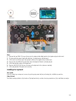
Page 55: ...at secure the keyboard bracket to the keyboard 5 Lift the keyboard bracket off the keyboard 6 Remove the 33 M1 2x1 6 screws that secure the keyboard to the palm rest assembly 7 Lift the keyboard off the palm rest assembly Installing the keyboard Prerequisite If you are replacing a component remove the existing component before performing the installation procedure About this task The following ima...

Page 56: ...56 ...

Page 57: ...Connect the keyboard backlight cable to the keyboard controller board 7 Replace the two M2x1 9 screws that secure the keyboard backlight cable to the keyboard controller board Next steps 1 Install the power button assembly 2 Install the system board 3 Install the right I O board 4 Install the left I O board 5 Install the battery 6 Install the rear I O cover 7 Install the 2230 solid state drive if ...

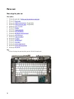
Page 58: ...e the rear I O cover 6 Remove the battery 7 Remove the display assembly 8 Remove the coin cell battery 9 Remove the keyboard controller board 10 Remove the left I O board 11 Remove the right I O board 12 Remove the speakers 13 Remove the system board 14 Remove the touchpad 15 Remove the power adapter port 16 Remove the power button assembly 17 Remove the keyboard Step After performing the pre requ...

Page 59: ...dapter port 4 Install the touchpad 5 Install the system board 6 Install the speakers 7 Install the right I O board 8 Install the left I O board 9 Install the keyboard controller board 10 Install the coin cell battery 11 Install the display assembly 12 Install the battery 13 Install the rear I O cover 14 Install the 2230 solid state drive if applicable 15 Install the 2280 solid state drive if appli...

Page 60: ...m www dell com support Intel Trusted Execution Engine Interface In the Device Manager check if the Intel Trusted Execution Engine Interface driver is installed Install the driver update from www dell com support Intel Virtual Button driver In the Device Manager check if the Intel Virtual Button driver is installed Install the driver updates from www dell com support Wireless and Bluetooth drivers ...

Page 61: ...alized This prompt can appear very quickly so you must watch for it and then press F2 If you press F2 before the F2 prompt this keystroke is lost If you wait too long and the operating system logo appears continue to wait until you see the desktop Then turn off your computer and try again Navigation keys NOTE For most of the System Setup options changes that you make are recorded but do not take e...

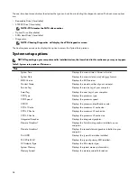
Page 62: ... Displays the BIOS version Product Name Displays the model number of your computer Service Tag Displays the service tag of your computer Asset Tag Displays the asset tag of your computer CPU Type Displays the processor type CPU Speed Displays the processor speed CPU ID Displays the processor identification code CPU L1 Cache Displays the processor L1 cache size CPU L2 Cache Displays the processor L...

Page 63: ...uter from Standby Default Disabled NOTE If USB PowerShare is enabled a device connected to the USB PowerShare connector may not wake the computer Sleep Mode Enable or disable sleep mode Intel Speed Shift Technology Enable disable Intel Speed Shift Technology support Setting this option to enable to allows the operating system to select the appropriate processor performance automatically Default En...

Page 64: ... status is unlocked Admin Password Status Displays if the administrator password is clear or set Default Not set System Password Status Displays if the system password is clear or set Default Not set HDD Password Status Displays if the HDD password is clear or set Default Not set Admin Password Enables you to set the administrator password The administrator password controls access to the system s...

Page 65: ... first boot option Boot Option 2 Displays the available second boot option Boot Option 3 Displays the available third boot option Table 9 System setup options Exit menu Exit Save Changes and Reset Allows you to exit system setup and save your changes Discard Changes and Reset Allows you to exit system setup and load previous values for all system setup options Restore Defaults Allows you to restor...

Page 66: ...m passwords To clear the system or BIOS passwords contact Dell technical support as described at www dell com contactdell NOTE For information on how to reset Windows or application passwords refer to the documentation accompanying Windows or your application 66 ...

Page 67: ...ostics front page is displayed 5 Click the arrow in the lower right corner to go to the page listing The items detected are listed 6 To run a diagnostic test on a specific device press Esc and click Yes to stop the diagnostic test 7 Select the device from the left pane and click Run Tests 8 If there are any issues error codes are displayed Note the error code and validation number and contact Dell...

Page 68: ...enabled Off Caps Lock disabled Flashing BIOS USB key 1 Follow the procedure from step 1 to step 7 in Flashing the BIOS to download the latest BIOS setup program file 2 Create a bootable USB drive For more information see the knowledge base article SLN143196 at www dell com support 3 Copy the BIOS setup program file to the bootable USB drive 4 Connect the bootable USB drive to the computer that nee...

Page 69: ...k If your computer is unable to access the internet due to WiFi connectivity issues a WiFi power cycle procedure may be performed The following procedure provides the instructions on how to conduct a WiFi power cycle NOTE Some ISPs Internet Service Providers provide a modem router combo device Steps 1 Turn off your computer 2 Turn off the modem 3 Turn off the wireless router 4 Wait for 30 seconds ...

Page 70: ...Search to retrieve the related articles Learn and know the following information about your product Product specifications Operating system Setting up and using your product Data backup Troubleshooting and diagnostics Factory and system restore BIOS information See Me and My Dell at www dell com support manuals To locate the Me and My Dell relevant to your product identify your product through one...

Reviews: