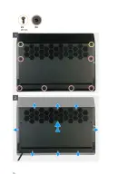


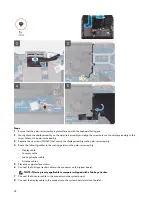


Steps
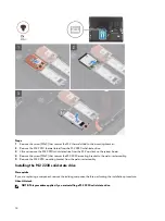
1
Peel and lift the Mylar covering the system board.
2 Disconnect and peel the Tron light cable from the system board and route the cable through the slot on the Mylar.
NOTE: To prevent damaging your computer ensure the Tron light cable has been disconnected from the system
board before removing the rear I/O-cover.
3 Remove the two screws (M2.5x5) that secure the rear I/O-cover to the palm-rest assembly.
4 Firmly grasp the sides of your computer with both hands and push the rubber feet on the rear I/O-cover outwards with
your thumbs to release the rear I/O-cover from the palm-rest assembly.
5 Lift the rear I/O-cover from the palm-rest assembly.
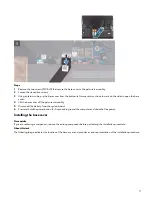
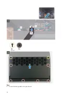
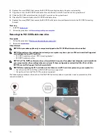
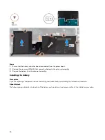
Installing the rear I/O-cover
Prerequisite
If you are replacing a component, remove the existing component before performing the installation procedure.
About this task
The following image indicates the location of the rear I/O-cover and provides a visual representation of the installation
procedure.
19
Summary of Contents for Alienware m15 R2
Page 1: ...Alienware m15 R2 Service Manual Regulatory Model P87F Regulatory Type P87F001 ...
Page 10: ...10 ...
Page 12: ...Steps 1 Connect the battery cable to the system board 12 ...
Page 40: ...40 ...
Page 43: ...43 ...
Page 56: ...56 ...