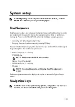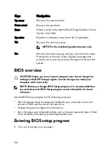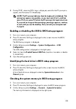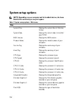
Enhanced Pre-Boot System Assessment
(ePSA) diagnostics
CAUTION: Use the ePSA diagnostics to test only your computer. Using
this program with other computers may cause invalid results or error
messages.
The ePSA diagnostics (also known as system diagnostics) performs a complete
check of your hardware. The ePSA is embedded with the BIOS and is launched by
the BIOS internally. The embedded system diagnostics provides a set of options for
particular devices or device groups allowing you to:
•
Run tests automatically or in an interactive mode
•
Repeat tests
•
Display or save test results
•
Run thorough tests to introduce additional test options to provide extra
information about the failed device(s)
•
View status messages that inform you if tests are completed successfully
•
View error messages that inform you of problems encountered during testing
NOTE: Some tests for specific devices require user interaction. Always
ensure that you are present at the computer terminal when the diagnostic
tests are performed.
For more information, see
Running the ePSA diagnostics
1
Power-on the computer.
2 As the computer boots, press the F12 key as the Dell logo appears.
3 On the boot menu screen, select the Diagnostics option.
4 Click the arrow key at the bottom left corner.
Diagnostics front page is displayed.
5 Press the arrow in the lower-right corner to go to the page listing.
The items detected are listed.
6 To run a diagnostic test on a specific device, press Esc and click Yes to stop
the diagnostic test.
7 Select the device from the left pane and click Run Tests.
146
Summary of Contents for Alienware 17 R5
Page 20: ...5 Replace the six screws M2 5x13 that secure the base cover to the computer base 20 ...
Page 23: ...7 Disconnect the interposer from the hard drive 23 ...
Page 26: ...7 Connect the hard drive cable to the system board Post requisites Replace the base cover 26 ...
Page 32: ...3 Slide and remove the solid state drive from the solid state drive slot 32 ...
Page 36: ...2 Slide and remove the memory module from the memory module slot 36 ...
Page 38: ...Post requisites Replace the base cover 38 ...
Page 40: ...3 Pull the rear I O cover from the computer base 40 ...
Page 42: ...Post requisites Replace the base cover 42 ...
Page 46: ...6 Lift the computer base off the palm rest assembly 46 ...
Page 51: ...5 Gently peel the coin cell battery along with its cable off the palm rest assembly 51 ...
Page 55: ...3 Lift the speakers along with its cable off the palm rest assembly 55 ...
Page 59: ...4 Turn the I O board over 5 Disconnect the subwoofer cable 59 ...
Page 60: ...6 Lift the I O board off the palm rest assembly 60 ...
Page 64: ...2 Lift the subwoofer along with its cable off the palm rest assembly 64 ...
Page 72: ...25 After performing all the above steps you are left with the system board 72 ...
Page 80: ...8 Lift the heat sink assembly off the system board 80 ...
Page 85: ...5 Remove the cable from the routing guides on the palm rest assembly 85 ...
Page 89: ...2 Lift the power button board along with its cable off the palm rest assembly 89 ...
Page 95: ...7 Lift the display assembly off the computer base 95 ...
Page 100: ...2 Lift the battery off the palm rest assembly 100 ...
Page 108: ...7 Replace the base cover 108 ...
Page 111: ...4 Peel off the macro keys cable and macro keys backlight cable from the keyboard 111 ...
Page 112: ...5 Lift the keyboard at an angle and remove it from the tabs on the palm rest assembly 112 ...
Page 116: ...13 Replace the base cover 116 ...
Page 122: ...Procedure After performing all the prerequisites we are left with the palm rest 122 ...
Page 124: ...19 Replace the base cover 124 ...


