Replacing the I/O board
WARNING: Before working inside your computer, read the safety
information that shipped with your computer and follow the steps in
. After working inside your computer, follow
the instructions in
After working inside your computer
. For more safety best
practices, see the Regulatory Compliance home page at
.
Procedure
1
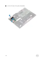
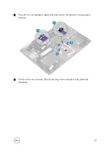
Place the I/O board on the palm-rest assembly and keyboard bracket.
2
Align the screw holes on the I/O board with the screw hole on the palm-rest
assembly and the screw hole on the keyboard bracket.
3
Replace the two screws (M2x2) that secure the I/O board to the keyboard
bracket.
4
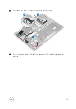
Connect the coin-cell battery cable to the I/O board.
5
Slide the I/O-board cable into the connector on the I/O board and close the
latch to secure the cable.
6
Adhere the adhesive tape covering the I/O-board cable connector on the I/O
board.
Post-requisites
1
Replace the
.
2
Replace the
.
47
Summary of Contents for 13 7000 2-in-1
Page 19: ...3 Lift the battery off the palm rest assembly 19 ...
Page 22: ...2 Peel the coin cell battery off the keyboard bracket 22 ...
Page 25: ...2 Lift the heat sink off the system board 25 ...
Page 28: ...4 Lift the fan off the keyboard bracket 28 ...
Page 31: ...5 Lift the right speaker off the palm rest assembly 31 ...
Page 34: ...3 Lift the power adapter port off the palm rest assembly 34 ...
Page 42: ...7 Gently lift the display assembly off the palm rest assembly 42 ...
Page 46: ...5 Lift the I O board off the palm rest assembly 46 ...
Page 54: ...14 Lift the system board off the palm rest assembly 54 ...
Page 62: ...5 Slide and lift the touchpad from the slot on the palm rest assembly 62 ...
Page 66: ...5 Lift the keyboard off the palm rest assembly 66 ...
Page 70: ...Procedure After performing all the prerequisites we are left with the palm rest 70 ...

