


Control panels
Left control panel view
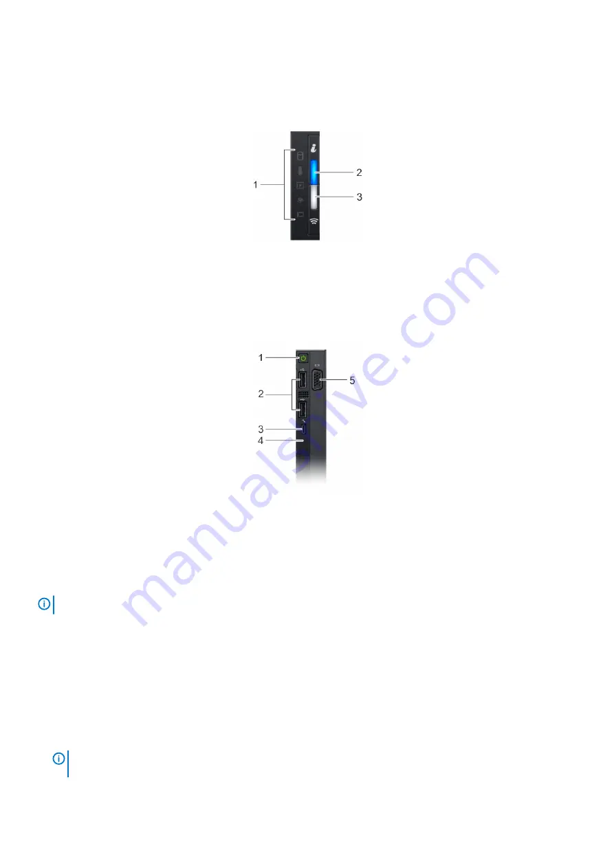
Figure 2. Left control panel view
1. Status LED indicators
2. System health and system ID indicator
3. iDRAC Quick Sync 2 wireless indicator (optional)
Right control panel view
Figure 3. Right control panel view
1. Power button
2. USB 2.0 port (2)
3. iDRAC Direct port
4. iDRAC Direct LED
5. VGA port
NOTE:
For more information on the ports, see
.
LCD panel
The LCD panel provides system information, status, and error messages to indicate if the system is functioning correctly or requires
attention. The LCD panel can also be used to configure or view the system’s iDRAC IP address. For information about the event and error
messages generated by the system firmware and agents that monitor system components, see the Error Code Lookup page at
.
The statuses and conditions of the LCD panel are outlined here:
•
The LCD backlight is white during normal operating conditions.
•
When the system needs attention, the LCD backlight turns amber, and displays an error code followed by descriptive text.
NOTE:
If the system is connected to a power source and an error is detected, the LCD turns amber regardless of
whether the system is turned on or off.
10
PowerEdge R940xa system overview