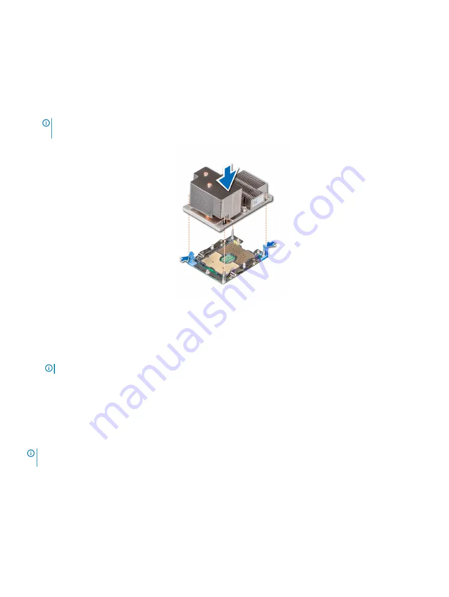
a Partially tighten the first screw (approximately 3 turns).
b Tighten the second screw completely.
c Return to the first screw and tighten it completely.
If the PHM slips off the blue retention clips when the screws are partially tightened, follow these steps to secure the PHM:
a
Loosen both the heat sink screws completely.
b
Lower the PHM on to the blue retention clips, following the procedure described in step 2.
c
Secure the PHM to the system board, following the replacement instructions listed in this step above. 4.
NOTE:
The processor and heat sink module retention screws should not be tightened to more than 0.13 kgf-m (1.35 N.m or
12 in-lbf).
Figure 64. Installing the processor and heat sink module (2U)
Next steps
1
If applicable,
.
NOTE:
If applicable, open the PCIe card holder latch on the air shroud to install the full length card.
2
Follow the procedure listed in
After working inside your system
.
Expansion cards and expansion card risers
Expansion card installation guidelines
NOTE:
A System Event Log (SEL) event is logged if an expansion card riser is not supported or missing. It does not prevent your
system from turning on. However, if a F1/F2 pause occurs and an error message is displayed.
The PowerEdge R740 system supports up to eight PCI express (PCIe) generation 3 expansion cards, that can be installed on the system
board using expansion card risers. The following table provides detailed information about the expansion card riser specifications:
Installing and removing system components
115
Summary of Contents for PowerEdge R740
Page 9: ...Figure 1 Supported configurations PowerEdge R740 system overview 9 ...
Page 28: ...Figure 22 NVDIMM battery and mid tray hard drives 28 PowerEdge R740 system overview ...
Page 141: ...Figure 94 Securing GPU 1 Installing and removing system components 141 ...
Page 142: ...Figure 95 Installing GPU 2 and 3 142 Installing and removing system components ...


