


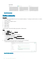


Map PowerEdge MX5016s storage sled drives
Assumptions
There are multiple configurations covered as part of this deployment guide. This section covers one specific example (listed below) out of
these possible configurations. The process for other configurations which include PowerEdge MX5016s would be very similar.
Following is the example configuration for PowerEdge MX7000:
•
2x PowerEdge MX7000 chassis
•
Each chassis includes:
– 2x PowerEdge MX740c compute sleds (2x SAS 2.5" SSD drives in each sled)
– 1x PowerEdge MX5016s storage sled with 8x SAS 2.5" SSD drives (4 drives for each compute sled)
NOTE:
This guide makes an assumption that the steps in this document are being followed comprehensively and sequentially. In
other words, the activities of previous sections are pre-requisites for this section.
Prerequisites
The following items are required to map PowerEdge MX5016s storage sled drives:
•
OME-M and iDRAC IP addresses or FQDNs
•
OME-M and iDRAC credentials
•
Storage sleds deployed, which includes SAS drives specified in
section
•
Compute sleds deployed
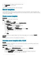
Map drives to compute sleds
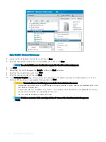
Drives in PowerEdge MX5016s storage sled can be mapped at the enclosure level (that is, entire sled) or individually (that is, one or more
specific drives) to the desired compute sleds.
About this task
Perform the following steps to map at the drive level:
Steps
1
Using a web browser, go to Open Manage Enterprise Modular (embedded chassis management) web interface at
https://<OME
Modular Address>
.
2
Log in with your credentials.
NOTE:
The default user name is
root
and the password is
calvin
.
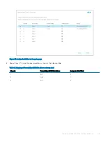
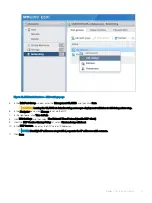
3
From the
Devices
menu, click
Storage
.
4
Click the required storage sled, for example,
Storage Sled 5
.
11
62
Map PowerEdge MX5016s storage sled drives
Summary of Contents for PowerEdge MX7000
Page 1: ...Dell EMC VMware Cloud Foundation for PowerEdge MX7000 Deployment Guide ...
Page 8: ...Figure 1 Cloud Foundation deployment workflow 8 Overview ...
Page 27: ...Figure 19 Dual PowerEdge MX7000 enclosure configuration Physical layout 27 ...
Page 29: ...Figure 20 MX9002m Management module cabling Physical layout 29 ...
Page 30: ...Figure 21 Connectivity between FSE modules and FEM modules 30 Physical layout ...
Page 31: ...Figure 22 Uplinks to customer network environment Physical layout 31 ...
Page 42: ...Figure 25 MX9002m Management Module cabling 42 Networking requirements ...
Page 43: ...Figure 26 Connectivity between FSE modules and FEM modules Networking requirements 43 ...
Page 44: ...Figure 27 Uplinks to customer network environment 44 Networking requirements ...


