


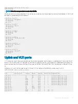


Configure the server facing ports
To support multiple VLANs, you must place the server facing ports in trunk mode. All the VLANs assigned to the ports are tagged to allow
the port groups to identify and direct traffic appropriately.
MX7K-IOM-A2# configure terminal
MX7K-IOM-A2(config)# interface range ethernet 1/1/1-1/1/8
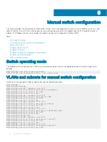
MX7K-IOM-A2(conf-range-eth1/1/1-1/1/8)# switchport trunk allowed vlan 96,1611-1614,2711-2712
MX7K-IOM-A2(conf-range-eth1/1/1-1/1/8)# mtu 9216
MX7K-IOM-A2(conf-range-eth1/1/1-1/1/8)# no shutdown
MX7K-IOM-A2(conf-range-eth1/1/1-1/1/8)# exit
MX7K-IOM-A2(config)# exit
MX7K-IOM-A2#
Save your switch configuration on each MX5108n switch by running the following command:
MX7K-IOM-A2#write mem
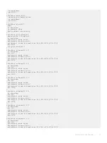
Verify switch configuration
The MX5108n switches are now configured with the minimum required settings to support the deployment of Cloud Foundation. Run the
running-config
command to verify the configuration. The configuration should look like:
! Version 10.4.0E.R3S
! Last configuration change at Mar 13 15:38:44 2019
!
snmp-server contact http://www.dellemc.com/support/softwarecontacts
hostname MX7K-IOM-A2
interface breakout 1/1/10 map 40g-1x
interface breakout 1/1/11 map 100g-1x
username admin password **** role sysadmin
aaa authentication local
iscsi target port 860
iscsi target port 3260
!
interface vlan1
no shutdown
!
interface vlan96
description Lab_Net
no shutdown
mtu 9216
!
interface vlan1611
description Management
no shutdown
mtu 9216
!
interface vlan1612
description VMotion
no shutdown
mtu 9216
!
interface vlan1613
description VSAN
no shutdown
mtu 9216
!
interface vlan1614
description "VXLAN NSX VTEP"
no shutdown
mtu 9216
!
interface vlan 2711
description Edge-Uplink
50
Manual switch configuration
Summary of Contents for PowerEdge MX7000
Page 1: ...Dell EMC VMware Cloud Foundation for PowerEdge MX7000 Deployment Guide ...
Page 8: ...Figure 1 Cloud Foundation deployment workflow 8 Overview ...
Page 27: ...Figure 19 Dual PowerEdge MX7000 enclosure configuration Physical layout 27 ...
Page 29: ...Figure 20 MX9002m Management module cabling Physical layout 29 ...
Page 30: ...Figure 21 Connectivity between FSE modules and FEM modules 30 Physical layout ...
Page 31: ...Figure 22 Uplinks to customer network environment Physical layout 31 ...
Page 42: ...Figure 25 MX9002m Management Module cabling 42 Networking requirements ...
Page 43: ...Figure 26 Connectivity between FSE modules and FEM modules Networking requirements 43 ...
Page 44: ...Figure 27 Uplinks to customer network environment 44 Networking requirements ...


