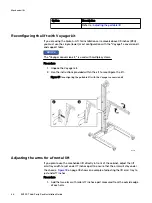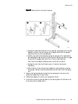
d. Attach the arm to the lift chassis by aligning the mounting holes, pressing
the plunger, and inserting the ball lock pins into the holes. Insert the top pin
first.
Figure 19 Adjusting the arm for a low rail position
CL5441
2. Remove the rotating handle by loosening the set screw and pulling the handle
from the hex fitting.
3. Using the cordless drill that comes with the Voyager conversion kit, place the
cordless drill over the hex fitting and use the drill to raise or lower the arm to
the required height.
4. Adjust the arm of the portable lift to the approximate height of the enclosure
you intend to move.
5. Attach the tray to the lift arm.
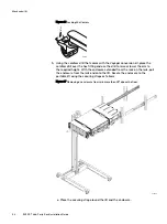
6. Lock all four casters by pressing down on the locking tab so the lift will not roll
as the instrument is placed onto it.
Figure 20 Locking the Casters
CL5423
7. Pull the enclosure onto the lift (, and then secure the enclosure to the portable
lift using the securing straps as follows:
Mechanical lift
50
EX300
Third-Party Rack Installation Guide
Summary of Contents for ECS EX300
Page 1: ...ECS EX300 Third Party Rack Installation Guide 302 005 206 02 ...
Page 6: ...FIGURES 6 EX300 Third Party Rack Installation Guide ...
Page 7: ...Planning your lift 46 1 TABLES EX300 Third Party Rack Installation Guide 7 ...
Page 8: ...TABLES 8 EX300 Third Party Rack Installation Guide ...
Page 13: ...Third Party Rack Installation Overview Components for EX300 systems 13 ...
Page 14: ...Third Party Rack Installation Overview 14 EX300 Third Party Rack Installation Guide ...
Page 17: ...Figure 1 PDU component location Rail Installation Dell EMC PDU rail and component location 17 ...
Page 42: ...Bring the system online 42 EX300 Third Party Rack Installation Guide ...

