

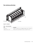


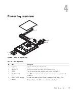

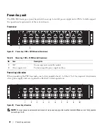


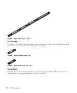


Power bay overview
22
Rear view
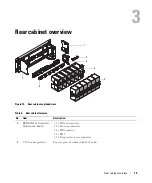
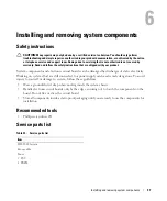
Figure 29. Power bay overview (rear view)
Table 17. Power bay overview (rear view)
No.
Item
Description
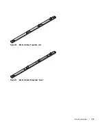
1
Rear IO
• RJ45 connectors (x 4)
• 1x5 connector (x 1)
• 1x6 connector (x 1)
• 2x8 connector (x 1)
2
Brush panel
Allows cabling to be fed to or from the rear of the cabinet and prevents dust
ingress.
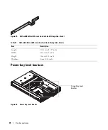
3
1U bus bar protector
Cover to prevent contact with the bus bar and an electrical short circuit.
4
Infrastructure module
• Includes RJ45 ports
• UID, power/status LEDS
• Reset button
• ICs: MCU, Ethernet switch, SPI ROM, EEPROM, TMP sensor, and RS232
driver/receiver
1
2
3
4
2


