


Power bay overview
19
4
Power bay overview
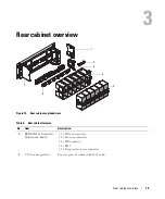
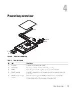
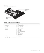
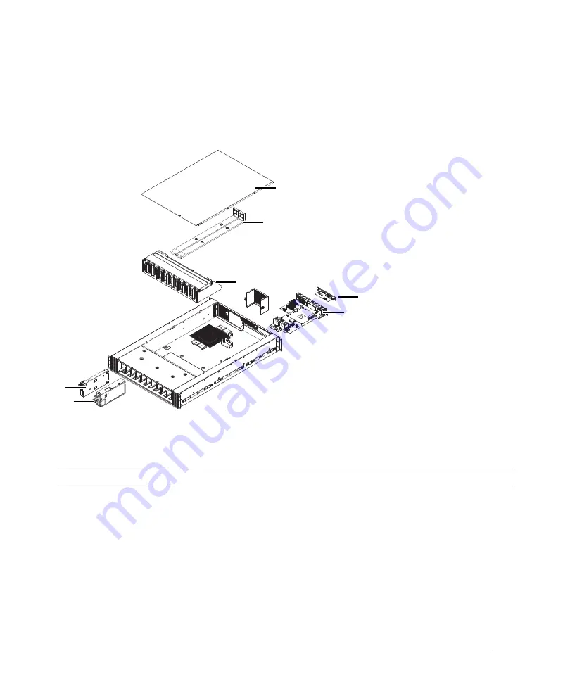
Figure 25. Power bay exploded view
Table 14. Power bay features
No.
Item
Description
1
Top cover
Top cover for the power bay chassis.
2
Bus Bar PB
Bar strip to conduct electricity within the power bay.
3
PBPM
Power bay power module regulates power control for the PSU.
4
Rear IO module
Four RJ45 connectors, one 1x5 connector, one 1x6 connector and one 2x8
connector.
5
DSS 9000 rack manager
module
Includes rack manager board (RMB) and infrastructure module (IM).
MC and blocks of the IM are networked through a LAN.
1
2
3
4
6
5
7


