DESIGNER’S HANDBOOK 4189350049C EN
Page 34 of 206
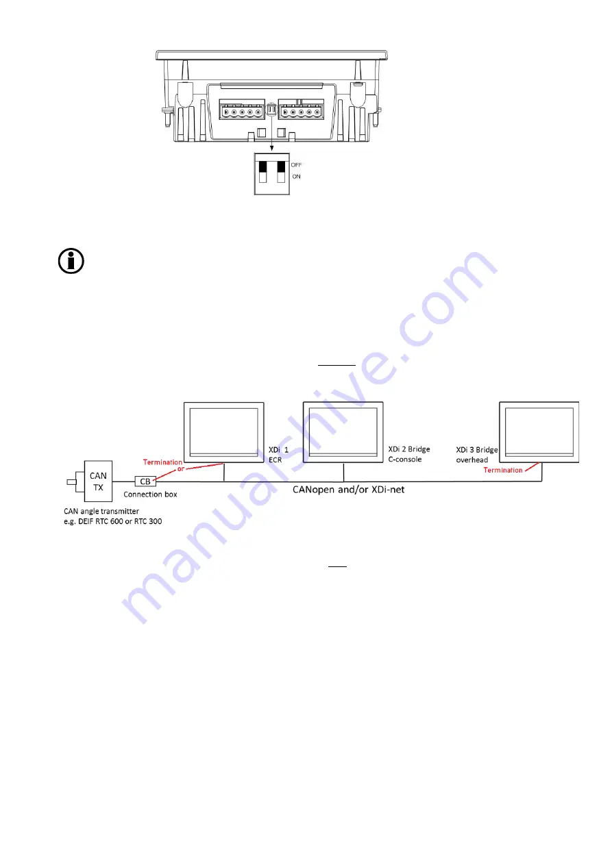
4.4.3.2 Termination example
This example shows a system where it can be considered where to insert the termination.
If the total cable from the CAN angle transmitter to XDi 1 exceeds the max allowed drop cable length (10 m @ 125
kbps), then a 120 Ω termination resistor should be installed in the connection box.
If the cable from the CAN TX (angle transmitter) to XDi 1 is less than the max allowed drop cable length (10 m @
125 kbps), then the CAN bus can be terminated by switching ON the internal termination resistor in XDi 1 (left
side), and the other termination can be made switching ON the internal termination in XDi 3 (right side).
4.4.3.3 Backbone and drop cable
The CAN bus backbone is the CAN bus cable between the two end-point terminations. In a practical installation,
terminations should be inserted in a way so that the most cable length will be serial-connected between the two
terminations. This cable will then be defined as the backbone. A cable section connected to the backbone in one
end and to a product in the other end, (without termination), is called a drop-cable. Drop-cables are not part of
the backbone, but the length of all drop-cables must be included in the total allowed CAN bus cable length.
4.4.4
CAN bus cable recommendation
Obtaining the optimal performance and cable length of the CAN bus requires the use of a good shielded CAN bus
cable. It may be a shielded single twisted pair, or it may be a single shielded cable containing 2 twisted pairs for
respectively data and power supply.
Only two termination resistors can be connected in a CAN bus network. Adding more
terminations will overload the CAN drivers, disturb communication and in the long run
maybe damage the CAN driver circuit.


