DESIGNER’S HANDBOOK 4189350049C EN
Page 195 of 206
*) The analogue RPM input can calculate %RPM based on actual RPM, and analogue pitch input is scaled to a
%Pitch value. (From the installation menu, an analogue pitch angle input can be scaled to %Pitch for indication). All
analogue data is default shared via the XDi-net.
**) You can disable the TPDO input in VS02 to make it only listen on XDi-net (it will function with TPDO active).
***) An AX1 module is needed on the XDi 2 to get the RPM set point. If the RPM set point is not used, then VS02
must be used for the XDi 2.
13.3 Application 3
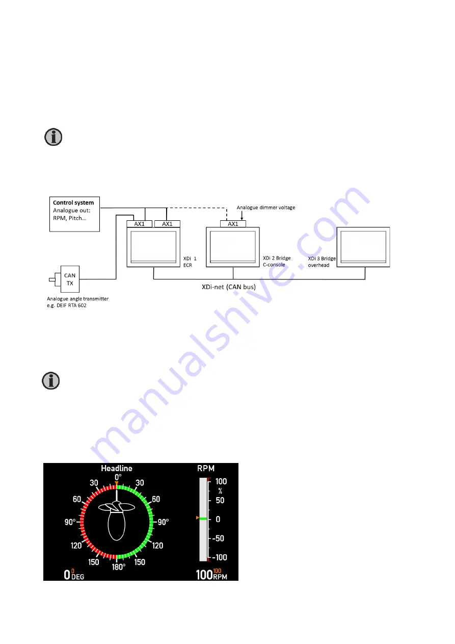
– azimuth analogue system using XDi-net
All inputs for this system are analogue, default they are 4 to 20 mA. All data is shared using the XDi-net protocol for
easy plug and play system integration.
Select a different NodeID for each of the 3 XDi indicators. Make sure that it is not already used by another CAN
device on the bus.
13.3.1
Azimuth and RPM indicator system with set point
This is the system above configured for azimuth angle and RPM/RPN% and with all set point data presented.
In this example, it is VI007 Pushing azimuth type with dynamic azimuth pointer and indi/- RPM/RPM%.
(Orange set points can be disabled from menu).
Presentation of set point (commanded value) for each data type must be activated via the menu; it
is by default OFF.
If you do not want set point (commanded value) data to be presented on the selected virtual
indicator, you must select “Visible: OFF” in the installation menu “Edit virtual indicator/indicators”.


