background image

OPERATOR & PARTS 

MANUAL

D E G E L M A N   I N D U S T R I E S   L T D.

B O X   8 3 0 - 2 7 2   I N D U S T R I A L   D R I V E ,

R E G I N A ,   S K ,   C A N A D A ,   S 4 P   3 B 1

F A X 306.543.2140 P H 3 0 6 . 5 4 3 . 4 4 4 7

1 . 8 0 0 . 6 6 7 . 3 5 4 5   D E G E L M A N . C O M
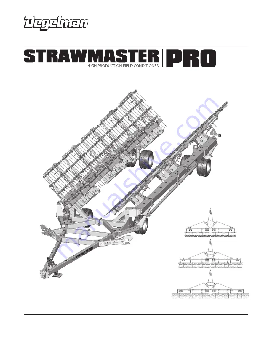
STRAWMASTER PRO

80’, 100’ & 120’

Serial Numbers: SM-7557 and up

142646 v2.2

Summary of Contents for STRAWMASTER PRO 100

Page 1: ... R I E S L T D B O X 8 3 0 2 7 2 I N D U S T R I A L D R I V E R E G I N A S K C A N A D A S 4 P 3 B 1 FA X 306 543 2140 P H 306 543 4447 1 8 0 0 6 6 7 3 5 4 5 D E G E L M A N C O M STRAWMASTER PRO 80 100 120 Serial Numbers SM 7557 and up 142646 v2 2 ...

Page 2: ......

Page 3: ... be activated again fully extended to close the clamps Note If Latches have been left in the down position the Swing Arms can also be engaged by allowing the Swing Arms to ride into the Latches and click into engagement Caution Lock hydraulic functions for both wing circuits before working in field to avoid accidental operation while in use 6 Lower the Harrow Sections down fully into field positio...

Page 4: ...wing Increasing this distance will raise front of the harrow section decreasing will lower it For initial setup and each time after you make adjustments to the harrow tine angles you should check and ensure that the harrow frame sections are running parallel to the ground Check that the front rows and back rows are applying equal pressure 298 NOTE If end of wing beam appears to be trailing back co...

Page 5: ...ansport Position 8 Adjustments 9 Service Maintenance Maintenance Checklist Specifications 12 Repair Hyd Cylinder Repair 15 Repair Pressed Bushing 16 Repair Wheel Hub 17 Repair Tine Replacement 18 Decal Location Overview 19 Troubleshooting 20 PARTS SECTION TABLE OF CONTENTS Part Assemblies Component Overview 21 Hitch Pole Frame Components 17 Wing Frame Beam Components 24 Link Arm Components 25 End ...

Page 6: ......

Page 7: ...Use this manual as your first source of information about this machine TO THE NEW OPERATOR OR OWNER Safe efficient and trouble free operation of your Degelman Strawmaster Pro requires that you and anyone else who will be operating or maintaining it read and understand the Safety Operation Maintenance and Troubleshooting information contained within this manual By following the operating instructio...

Page 8: ...tions are not taken WARNING Indicates a potentially hazardous situation that if not avoided COULD result in death or serious injury if proper precautions are not taken CAUTION Indicates a potentially hazardous situation that if not avoided MAY result in minor or moderate injury if proper practices are not taken or serves as a reminder to follow appropriate safety practices Why is SAFETY important ...

Page 9: ...on who has not read and understood all operating and safety instructions is not qualified to operate the machine An untrained operator exposes himself and bystanders to possible serious injury or death Do not modify the equipment in any way Unauthorized modification may impair the function and or safety and could affect the life of the equipment Think Safety Work Safely SAFETY 1 Read and understan...

Page 10: ...rm Latch Assembly BRIEF OVERVIEW OF OPERATION Operating speed will depend on tractor horsepower environmental conditions and each particular operation A speed of 8 to 12 MPH 12 to 16 KPH is suggested to efficiently shatter and spread straw and residue Operating height for the harrow will vary with the length of the tines and the angle that the tines are set at The harrow sections can be set in flo...

Page 11: ...tainer such as a Klik pin is installed NOTE It is important to pin the draw bar in the central location only Check tires and ensure that they are inflated to the specified pressure 41 PSI 283 kPa Ensure that a safety chain on the hitch is installed Check oil level in the tractor hydraulic reservoir Top up as required Check all bolt tightness Inspect all hydraulic lines hoses fittings and couplers ...

Page 12: ...nition key before dismounting 5 Connect the hydraulics To connect proceed as follows Use a clean cloth or paper towel to clean the couplers on the ends of the hoses Also clean the area around the couplers on the tractor Remove the plastic plugs from the couplers and insert the male ends Be sure to match the pressure and return line to one valve bank 6 Use the hydraulic jack to raise or lower the h...

Page 13: ...and continue to back into position 5 When the Autofold Swing Arms are close to closing you can activate the End Wheel Cylinder Circuit again to open the Latch Clamp 6 Then when the Swing Arms are in latched position this circuit can be activated again fully extended to close the clamps NOTE If the latches have been left in the down position the Swing Arms can also be engaged by allowing the Swing ...

Page 14: ... transport laws when transporting Operation FIELD TO TRANSPORT POSITION x8 x2 TRANSPORT SAFETY 1 Check with local authorities regarding machine transport on public roads Obey all applicable laws and regulations 2 Always travel at a safe speed Use caution when making corners or meeting traffic 3 Maximum Recommended Transport Speed 50 km h or 30 mph Road Conditions Field speeds may be lower 4 Make s...

Page 15: ...le in contact with moist soil Avoid straw build up in the first two rows of tines This makes for a more even granule or seed broadcast IMPORTANT Always follow label directions for chemical herbicides CHEMICAL INCORPORATION 4 3 2 1 REMEMBER Actual settings will vary with tine wear Straw should be dry Breaking down straw is much more effective in dry conditions A second pass may be required in extre...

Page 16: ...ENT Lift Harrow Sections Relieves Tension on Springs 2 Loosen the top Jam nut Arms to allow adjustment Top Jam Nut Adjustment Arm To Loosen 4 Re tighten top Jam nut Arms Top Jam Nut Adjustment Arm To Tighten Depending on tine angle settings and tine wear the parallel adjustment distances may need to be adjusted to ensure harrow sections are running parallel Remember Increasing the parallel adjustm...

Page 17: ...r rod is exposed 4 Parallel Adjustment Distance set to 4 1 1 2 of Exposed Rod Cylinder Locked Cylinders Locked Increases Downward Pressure on Harrow Section Aggressive Harrowing Setting Parallel Adjustment setting should be set to 5 The harrow cylinders should be set in float position 5 Cylinder in Float Position Parallel Adjustment Distance set to 5 Floating with Standard Weight of Harrow Section...

Page 18: ... Leaks Damaged Hoses Check Tire Pressure Tires 550 45 x 22 5 41 PSI 283 kPa Weekly 25 Hours Wheel Cylinder Pins Pivot Bushing Ratchet Jack Pins Check Tine Wear Clean Safety Signs Annually 200 Hours Bolt Tightness Wheel Bearings Latch Mechanism TORQUE all hardware MAINTENANCE SCHEDULE MAINTENANCE SAFETY Review the Operator s Manual and all safety items before working with maintaining or operating t...

Page 19: ...1290 1545 2095 1 3 8 1250 1695 2025 2745 1 1 2 1650 2245 2690 3645 METRIC TORQUE SPECIFICATIONS Coarse Thread based on Zinc Plated values 8 8 10 9 Size Class 8 8 Class 10 9 lb ft N m lb ft N m M6 7 10 10 14 M8 16 22 23 31 M10 30 42 45 60 M12 55 75 80 108 M14 90 120 125 170 M16 135 185 195 265 M18 190 255 270 365 M20 265 360 380 515 M22 365 495 520 705 M24 460 625 660 895 M27 675 915 970 1315 M30 9...

Page 20: ...o help the O ring slide past the port entrance corner and avoid damaging it 4 Screw the fitting into position tighten to proper torque value from the table shown above Adjustable Port End Assembly 1 Inspect the components to ensure male female threads and sealing surfaces are free of nicks burrs scratches or any foreign material 2 Ensure O Ring seal is properly installed and undamaged 3 Lubricate ...

Page 21: ...pect the inside of the cylinder barrel piston rod and other polished parts for burrs and scratches Smooth areas as needed with an emery cloth REASSEMBLY 1 Reinstall rod through end cap gland assembly 2 Secure piston to rod with lock nut Torque lock nut to proper value refer to chart for proper torque value 3 Lube inside of barrel piston seals and gland seals with hydraulic oil 4 With cylinder body...

Page 22: ... the location for the new bushing insert 5 Ensuring the bushing is properly aligned press into hole preferred method or hammer into position by striking the stepped tool 6 Continue to install until the bushing edge is recessed in to a distance of 5 16 to allow for the outer seal to be properly installed Do not exceed this depth 7 Repeat procedure for bushing on opposite side 8 When both bushings a...

Page 23: ...position 10 Pump grease into hub through grease fitting until lubricant can be seen from dust seal COMMON HUB SPINDLE COMPONENTS Dust Seal Inner Cone Inner Cup Hub Outer Cup Outer Cone Flat Washer Slotted Nut Cotter Pin Dust Cap Spindle IMPORTANT Be sure to block up unit securely before removing tires Wheel Tightening Procedure 1 Install and hand tighten nuts bolts 2 Tighten to approx 20 Torque va...

Page 24: ...tall bolts and nuts 3 Position pipe between the brackets on the sides of the frame with the lug on the outside of the frame Install the spacer and bolt secure with locknut Ensure pipe turns freely when tightening 4 Line up hole on lug with hole on link bar install bolt and secure with nut 5 Back row Install pin through the jack and lug Secure with hair clip 6 See the adjustments section and adjust...

Page 25: ...l Reflector Red 2 x 9 2 142650 Decal Fluorescent Tape 2 x 9 2 Keep safety decals and signs clean and legible at all times Replace safety decals and signs that are missing or have become illegible Safety decals or signs are available from your Dealer Parts Department SAFETY DECALS REFLECTORS 143569 Decal Strawmaster Pro 2 Both Sides 143327 Decal Important Backup 2 Both Sides 142989 Decal Hyd Hoses ...

Page 26: ...Observe if sections creeps down If not repair tractor hydraulics Harrow sections raise too slowly Hydraulic pressure from tractor too low Restriction in hose External hydraulic leak Check pressure should be 2500 psi Disconnect blow out lines with compressed air Repair as needed Oil accumulation on cylinder shaft Hydraulic cylinder leak Oil bypassing seals Replace seals or damaged components Seal m...

Page 27: ...heel RH Tread Swing Arm Latch Front Beam Assembly Back Beam Inner Link Arm Assembly Hydraulic Mount Jack Assembly RH WING LH WING Back Beam Outer 100 120 Harrow Section End Wheel Assembly Front Cart Assembly 135 6 4 2 9 8 EXPLODED COMPONENT OVERVIEW 100 Strawmaster Pro Shown 80 Strawmaster Pro 120 Strawmaster Pro 100 120 80 80 C L C L ...

Page 28: ...51 Bolt 3 4 x 3 GR8 8 118422 Lock nut 3 4 8 141597 Ball Valve 3 4 ORB 1 123412 Cylinder Monarch 4 x 8 x 2 1 Seal Kit 123049 573180 Jack Base Pad Assembly 1 573175 Jack Leg Assembly 1 573341 Pin 2 x 7 9 16 4 117416 Lock Nut 7 8 Unitorque 4 118774 Flat Washer 7 8 F436 8 118727 Bolt 7 8 x 2 1 2 4 Front Hitch Components 248535 Pole Assembly RH 1 248740 Front Hitch Plate 1 124027 Hitch CAT 5 1 118073 B...

Page 29: ...Tire 550 45 22 5 1 131863 Rim 22 5 x 16 8H 1 118794 Bolt 1 2 x 5 4 118420 Lock nut 1 2 unitorque 4 comes with Tire Pressure 41 PSI 283 kPa Wheel Components 248610 Latch Assembly 2 248715 Pin Assembly 2 x 10 2 247449 Pin 1 1 4 x 4 1 2 2 247703 Latch Adjustment Rod 2 810280 Retaining Ring 8 118456 Lock Nut 1 2 143506 Spring 2 OD 2 123076 Cylinder Monarch 2 x 4 x 1 1 4 1 Seal Kit 123061 117225 Bushin...

Page 30: ...Arm Clamp x2 x2 x2 x2 x2 x2 x2 x2 x2 x1 x2 x1 x1 x1 248690 Back Beam Assembly Inner 2 248700 Back Beam Assembly Outer 120ft 2 247500 Harrow Section Assembly Complete 12 120 ft 248620 Front Beam 2 120 Beam Link Arm Assembly 8 Cross Joint End Wheel Pivot Assembly LH Truss Arm Clamp x2 x2 x2 x2 x2 x2 x2 x2 x2 x2 x2 x1 x1 x1 x1 780278 Hose Clamps 3 8 1 118144 Bolt 5 16 x 1 1 2 1 780279 Top Plate 1 780...

Page 31: ... 16 SQ 1 247765 Link Unit Clamp 1 117225 Bushing 2 1 2 OD x 2 4 133135 Wiper Seal 2 1 2 OD 4 Cylinder Replacement Bushings 118024 Bolt 5 8 x 1 1 2 4 118508 Lock washer 5 8 4 117462 Flat washer 5 8 4 123725 Cylinder Monarch 4 x 24 x 2 1 Seal Kit 123049 248715 Pin Assembly 2 x 10 4 247777 Clamp Plate 1 248670 Back Beam Holder 1 117225 Bushing 2 1 2 OD x 2 5 133135 Wiper Seal 2 1 2 OD 6 248680 Hyd Li...

Page 32: ...ansport Wheel Clamp 1 248730 Transport Wheel Holder 1 247745 Collar 1 118708 Bolt 5 8 x 10 1 118775 Flat washer 3 4 F436 16 118051 Bolt 3 4 x 3 GR8 8 118447 Lock nut 5 8 unitorque 1 118422 Lock nut 3 4 8 131776 Wheel nut 5 8 UNF GR8 16 131735 Hub Spindle Assembly HA817 2 131521 Valve Stem TR501 1 131862 Tire 550 45 22 5 1 131863 Rim 22 5 x 16 8H 1 Endwheel Pivot Assembly Overview LH Orientation Sh...

Page 33: ...Harrow Section Overview 118700 Lock nut 5 8 UNF 4 244017 Indicator pointer 1 244217 Link bar 4 hole 1 118625 Bolt 5 8 x 2 UNF 4 118094 Bolt 5 8 x 4 4 118630 Bolt Bent 3 4 x 12 1 2 2 118119 Bolt 3 4 x 4 2 650250 Cast Shank Bolt Bar 2 243333 Bar Spring Steel 2 243061 Bar Back up 2 243055 Frame holder 2 118509 Lock washer 3 4 2 118508 Lock washer 5 8 4 118775 Flat washer 3 4 F436 4 118410 Nut 3 4 2 1...

Page 34: ...equired Hoses for Latch Steering Cylinders 126723 Hose 3 8 x 40 1 2 ORFS F SW 4 40 126732 Hose 3 8 x 348 1 2 ORFS F SW 4 348 126736 Hose 3 8 x 480 1 2 ORFS F SW 4 600 480 126801 Hose 3 8 x 600 1 2 ORFS F SW 4 80 Model Only 100 Models Only 141676 Connector 3 4 ORB M x M 4 141686 Coupler Brown 1 141687 Coupler Brown 1 141683 Coupler Blue 1 141682 Coupler Blue 1 141703 Adaptor 1 2 ORB M x ORFS M 4 34...

Page 35: ...6733 Hose 3 8 x 456 1 2 ORFS F SW 4 456 126727 Hose 3 8 x 110 1 2 ORFS F SW 2 110 126800 Hose 3 8 x 198 1 2 ORFS F SW 4 126724 Hose 3 8 x 48 1 2 ORFS F SW 4 80 or 8 48 126726 Hose 3 8 x 72 1 2 ORFS F SW 4 80 or 8 72 80 Model Only 100 Models Only 100 120 Models Only NOTE RH has the same Hoses Fitting layout as LH Wing 141676 Connector 3 4 ORB M x M 2 141581 Coupler Tip 3 4 ORB F 2 141684 Coupler Gr...

Page 36: ...1 141597 Ball Valve 3 4 ORB F 1 141676 Connector 3 4 ORB M x M 2 141581 Coupler Tip 3 4 ORB F 2 141688 Coupler Black 1 141689 Coupler Black 1 141703 Adaptor 1 2 ORB M x ORFS M 2 130 116 9 122668 Orifice 3 4 16 UNF 1 5 116 130 10 5 1 2 4 5 1 2 3 5 5 11 9 10 141705 Elbow 90º 1 2 ORB M x ORFS F SW 1 6 141704 Elbow 90º 1 2 ORB M x ORFS M 1 6 123412 Cylinder Monarch 4 x 8 x 2 1 Seal Kit 123049 IMPORTAN...

Page 37: ...Unitorque 8 118123 Bolt 1 4 x 1 8 129127 Lamp Amber LED Single 1 244876 Light Bracket Single Amber 1 118009 Bolt 1 2 x 1 1 4 2 Right End Beam Amber LED Light Components 118420 Lock Nut 1 2 2 118483 Lock Nut 1 4 Unitorque 4 118123 Bolt 1 4 x 1 4 129126 Lamp Brake LED RH 1 118010 Bolt 1 2 x 1 1 2 2 118512 Flat washer 1 2 2 248668 Bracket Dual Light RH 1 Right End Beam Dual LED Light Components 11842...

Page 38: ...plies rental machinery or loss of use No other warranty of any kind whatsoever express or implied is made with respect to this sale and all implied warranties of merchantability and fitness for a particular purpose which exceed the obligations set forth in this written warranty are hereby disclaimed and excluded from this sale This exclusion shall not apply in any jurisdiction where it is not perm...

Page 39: ...r service or replacement of defective parts which are covered by warranty Repairs to be submitted for warranty consideration must be made within forty five days of failure It is the Retail Customer s responsibility for any cost incurred by the dealer for hauling of the product for the purpose of performing a warranty obligation or inspection WARRANTY INFORMATION Make certain the warranty registrat...

Reviews: