DeDietrich IniControl Installation, User And Service Manual Download Page 20

5.4

Changing the settings

5.4.1.

General

The boiler control panel is set for the most common heating

systems. With these settings, practically all heating systems operate

correctly. The user or installer can optimise the parameters according

to own preferences.

For the settings of the 

C630 Eco

 boiler: The parameters

and settings described are for each boiler module. Each

parameter changing must therefore be done identical on

each module.

5.4.2.

Parameter descriptions
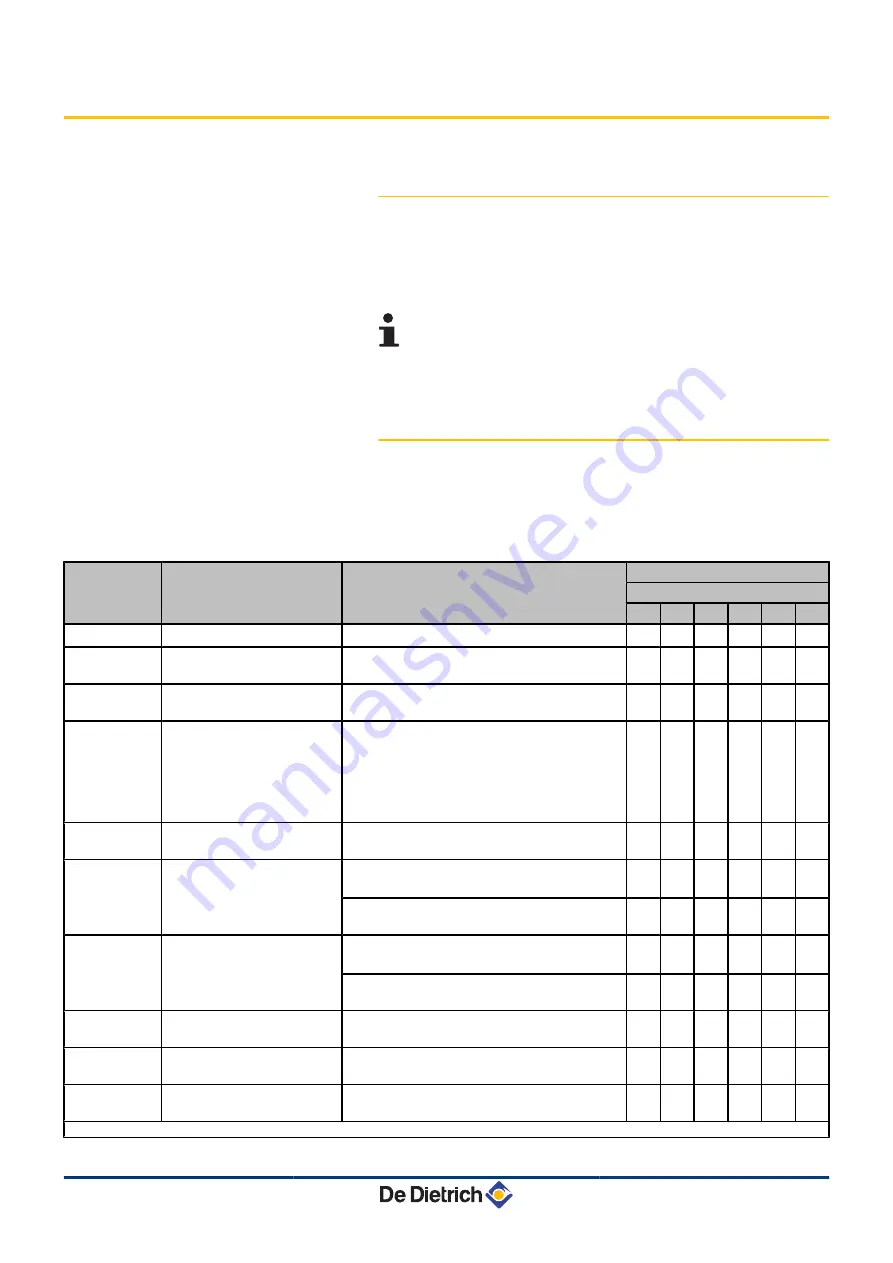
n

Boiler type C 330 ECO

Parameter

Description

Adjustment range

Factory setting
C 330 ECO
280 350 430 500 570 650

p1

Flow temperature:  T

SET

20 to 90 °C

80

80

80

80

80

80

p2

Post-circulation of the pump 1 to 98 minutes

99 minutes = continuous

5

5

5

5

5

5

p3

Boiler regulation

0 = Heating deactivated

1 = Heating activated

1

1

1

1

1

1

p4

Display screen

0 = Simple

1 = Comprehensive

2 = Automatic switching to simple after 3

minutes

3 = Automatic switching to simple after 3

minutes; Key blocking is active

2

2

2

2

2

2

p5

Brightness of display lighting 0 = Dimmed

1 = Bright

1

1

1

1

1

1

p17

Maximum fan speed

G25 (Gas L)

(1)

(x100 rpm)

53

56

35

38

43

42

G20 (Gas H)

(x100 rpm)

52

55

35

38

43

41

p18

Minimum fan speed

G25 (Gas L)

(1)

(x100 rpm)

14

15

9

10

11

10

G20 (Gas H)

(x100 rpm)

14

15

9

10

11

10

p19

offset Minimum fan speed

Do not modify

(x1 rpm)

0

50

50

50

0

50

p20

Start speed

Do not modify

(x100 rpm)

25

25

13

14

14

14

p21

Maximum flow temperature

of system

0 to 90 °C

90

90

90

90

90

90

(1) Do not modify these factory settings unless absolutely necessary. E.g. to adapt the boiler to: G20 (Gas H)

5. Commissioning

IniControl For C 330 / C 630 ECO

19

260216 - 7600717-001-06

Summary of Contents for IniControl

Page 1: ...Ireland EN Regulation IniControl For C 330 C 630 ECO C003108 A Installation User and Service Manual 7600717 001 06...

Page 2: ...nsor 9 4 2 1 Choice of the location 9 4 2 2 Connecting the outside sensor 10 4 3 Fitting and connecting the control panel 10 4 4 Electrical connections 11 4 4 1 Connecting a direct heating circuit 11...

Page 3: ...5 4 5 Setting the maximum heat input for central heating operation 25 5 4 6 Return to the factory settings Reset Param 26 5 4 7 Carrying out an auto detect 26 5 4 8 Setting the manual mode 27 6 Troubl...

Page 4: ...3 260216 7600717 001 06...

Page 5: ...cal injury WARNING Risk of a dangerous situation causing slight physical injury CAUTION Risk of material damage Signals important information Signals a referral to other instructions or other pages in...

Page 6: ...compliance with the prevailing legislation and standards 4 Perform the initial start up and carry out any checks necessary 4 Explain the installation to the user 4 If a maintenance is necessary warn t...

Page 7: ...re that children do not play with the appliance If the mains power lead is damaged it must be replaced by the original manufacturer the manufacturer s dealer or another competent person to prevent haz...

Page 8: ...and heating equipment must be carried out by a qualified engineer For a proper operating of the boiler follow carefully the instructions Keep this document close to the place where the boiler is inst...

Page 9: ...1342 1149 984 842 720 616 528 454 Specifications of the flow sensor circuit B C Specifications of the DHW sensor Specifications of the system sensor Temperature in C 0 10 20 25 30 40 50 60 70 80 90 Re...

Page 10: ...sensor FM46 RX11 cable AD124 Modulating room thermostat AD265 Radio controlled modulating room thermostat AD266 Digital room thermostat AD137 Wireless settable ambient thermostat AD200 SCU S05 PCB SC...

Page 11: ...uptive heat source sun chimney ventilation grid etc 4 2 2 Connecting the outside sensor Mount the sensor using the screws and dowels provided A Inserts Z 4 wood screw For the connection of the outside...

Page 12: ...afety thermostat to the connector 4 4 2 Connection in cascade with OpenTherm AD287 option A Master boiler DIEMATIC iSystem Z Secondary boiler DIEMATIC iSystem or IniControl E Secondary boiler DIEMATIC...

Page 13: ...he Opentherm from the PCU to the Opentherm on the interface P OpenTherm AD287 interface board to be fitted in the boiler control panel a Encoding wheel used to set the addresses of the slave boilers S...

Page 14: ...or Manual reset t B Heating temperature button d or C DHW temperature button r or D S Enter Key E Chimney sweeping keys Press keys A and B simultaneously F f Menu keys Press keys C and D simultaneousl...

Page 15: ...tivated r State DHW pump S DHW off m Manual mode m The DHW function is in economic mode deactivated g Boiler protection is active n Flame output level e Low output level 0 25 r Average output level 25...

Page 16: ...and switched on again before resetting I Outside temperature sensor present M The symbol is displayed when the boiler pump is operating a Defect Boiler indicates a fault This is indicated by an E code...

Page 17: ...lay Check the mains supply voltage Check the main fuses Check the fuses on the control panel F1 2 AT F2 8 AT Check the connection of the mains lead to the connector in the instrument box 4 A fault is...

Page 18: ...from the hour counter and percentage of successful starts 1 Press the two keys f simultaneously and then key until the symbol flashes on the menu bar 2 Press the S key hr and the number of hours of bo...

Page 19: ...nal set point 32 Output control 33 Temperature protection gradient level 1 Modulate down 34 Temperature protection gradient level 2 Part load 35 Temperature protection gradient level 3 Blockage 36 Mod...

Page 20: ...tinuous 5 5 5 5 5 5 p3 Boiler regulation 0 Heating deactivated 1 Heating activated 1 1 1 1 1 1 p4 Display screen 0 Simple 1 Comprehensive 2 Automatic switching to simple after 3 minutes 3 Automatic sw...

Page 21: ...HdV If connected 0 to 255 seconds 0 0 0 0 0 0 p31 Flue gas damper running time FgV If connected 0 to 255 seconds 0 0 0 0 0 0 p32 Release waiting time 0 to 255 seconds 0 0 0 0 0 0 p33 Gas valve leak p...

Page 22: ...Adjustment range Factory setting C 630 ECO 560 700 860 1000 1140 1300 p1 Flow temperature TSET 20 to 90 C 80 80 80 80 80 80 p2 Post circulation of the pump 1 to 98 minutes 99 minutes continuous 5 5 5...

Page 23: ...cted 0 0 0 0 0 0 p30 Hydraulic valve running time HdV If connected 0 to 255 seconds 0 0 0 0 0 0 p31 Flue gas damper running time FgV If connected 0 to 255 seconds 0 0 0 0 0 0 p32 Release waiting time...

Page 24: ...0 10 10 10 10 10 p45 TModulate down 10 to 30 C 25 25 25 25 25 25 Zd Detection of connected SCUs 0 No detection 1 Detection 0 0 0 0 0 0 df and dV Factory setting To restore the factory settings or when...

Page 25: ...es to return to the current operating mode The parameters p002 to p007 are changed in the same way as p001 After step 2 use the key to move to the required parameter 5 4 4 Modification of the installe...

Page 26: ...operating status if no keys are pressed for 3 minutes 5 4 5 Setting the maximum heat input for central heating operation The speed can be changed using parameter p17 To do this proceed as follows 1 P...

Page 27: ...for CN2 Check this against the value of Y on the type plate 9 Enter the value of Y shown on the type plate using the or key 10 Confirm the value with the j key The factory settings are reset 11 The di...

Page 28: ...the menu bar 2 Press the S key or The text Zv with the current water pressure only if an outside sensor is connected The flow temperature is determined by the internal heating curve or The value of th...

Page 29: ...rs with Recom 5v 1 Maximum flow temperature exceeded The water flow in the installation is insufficient 4 Check the circulation direction pump valves 5v 2 Maximum increase of the flow temperature has...

Page 30: ...error 4 Reset df and dV 4 Restore parameters with Recom Bad connection 4 Check the wiring 5v 9 Phase and neutral of mains supply mixed up 4 Mains supply incorrectly wired 4 Floating or 2 phase network...

Page 31: ...tting of the gas valve unit 4 Check that the air inlet and flue gas discharge flues are not blocked 4 Check that there is no recirculation of flue gases 5v 25 Internal error on the SU PCB 4 Replace th...

Page 32: ...pump valves 4 Check the water pressure 4 Check the cleanliness of the heat exchanger e 05 Exchanger temperature too high Bad connection 4 Check the wiring between the PCU PCB and the sensor 4 Check t...

Page 33: ...he heating system 4 Check the circulation direction pump valves 4 Check the water pressure 4 Check the cleanliness of the heat exchanger e 10 Difference insufficient between the exchanger temperature...

Page 34: ...he ignition transformer 4 Check that the SU PCB is correctly in place 4 Check the ionization ignition electrode 4 Check the earthing 4 SU PCB faulty Change the PCB Ignition arc but no flame formation...

Page 35: ...turn reversed Bad connection 4 Check that the sensor has been correctly fitted Sensor fault 4 Check the Ohmic value of the sensors 4 Replace the sensor if necessary Water circulation direction reverse...

Page 36: ...lers menu using the key S c0de appears on the display 3 Use keys or to input the installer code 0012 4 Press the S key er xx appears on the display 5 The fault list or shutdown list can be displayed b...

Page 37: ...The fault list or shutdown list can be displayed by pressing the or key 6 Confirm using key S er xx is displayed with xx flashing 7 Press the key several times until er cl is displayed on the screen 8...

Page 38: ......

Page 39: ......

Page 40: ...0 271 001 627 dedietrich bdrthermea cz IT DE DIETRICH THERMIQUE Iberia S L U www dedietrich calefaccion es C Salvador Espriu 11 08908 L HOSPITALET de LLOBREGAT 34 935 475 850 info dedietrich calefacci...

Reviews: