background image

T

ABLE


OF

 C

ONTENTS

Chapter 1
Introduction.............................................................. 1

EtherSeries EDNP-3 Functions.................................... 2
Other Features.............................................................. 2
Physical Details............................................................ 3

Configuration Switch ............................................4
LED Indicators...................................................... 4
Software Requirements..........................................5

Chapter 2
Installation................................................................ 7

Overview...................................................................... 7
Quick Start....................................................................7
Installation.................................................................... 8

Chapter 3
Terminal/Telnet
Configuration............................................................ 9

Overview...................................................................... 9
Terminal Configuration.............................................. 10

Procedure.............................................................10

Telnet Management.................................................... 11
Terminal/Telnet Interface...........................................13
Entering Data..............................................................14
Menu Options............................................................. 14

i

Summary of Contents for EtherSeries EDNP-3

Page 1: ...EtherSeries DNP 3 Gateway EDNP 3 User s Guide Revised January 16 2008 Firmware Version 3 x...

Page 2: ......

Page 3: ...ept any interference received including interference that may cause undesired operation CE Marking Warning This is a class B product In a domestic environment this product may cause radio interference...

Page 4: ...ii...

Page 5: ...3 Configuration Switch 4 LED Indicators 4 Software Requirements 5 Chapter 2 Installation 7 Overview 7 Quick Start 7 Installation 8 Chapter 3 Terminal Telnet Configuration 9 Overview 9 Terminal Configu...

Page 6: ...Option 7 Security Configuration 21 Main Menu Option 8 SNMP Configuration 23 Main Menu Option 9 Display Configuration Settings 24 Main Menu Option R Reset Configuration to Default 26 Main Menu Option S...

Page 7: ...40 Configuration Security 40 Overview 40 Level 0 41 Level 1 42 Level 2 42 Level 3 42 Chapter 7 Troubleshooting 45 Hardware Problems 45 Can t Connect via the LAN 46 Other Problems 48 Verify Proper Oper...

Page 8: ...Appendix B RS 422 RS 485 Interface 57 Introduction 57 Changing the Setting 57 RS 422 4 Wire RS 485 Interface Pinout 58 2 Wire RS 485 Interface Pinout 59 RS 485 2 wire Fan out 59 iv...

Page 9: ...Introduction v...

Page 10: ......

Page 11: ...s ports DNP 3 has been extended to operate over Ethernet using the IP protocol suite This gateway converts between the DNP 3 IP protocol and DNP 3 Serial protocols transparently Normal operation would...

Page 12: ...3 ethernet based controllers to communicate with DNP 3 based serial RTUs It will not allow DNP 3 IP RTUs to operate with a serial DNP 3 controller Other Features Dual Serial Ports The EDNP 3 contains...

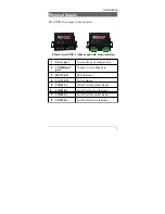
Page 13: ...solation 1 Power port Connect the power adapter here 2 10 100Base T port Connect LAN cabling here 3 RUN LED RUN Indicator 4 LAN LED LAN Indicator 5 COM1 Tx Serial Port Transmit Indicator 6 COM1 Rx Ser...

Page 14: ...s switch may be depressed with a tiny screw driver or stiff wire A straightened paper clip works nicely LED Indicators There are six red LED indicators on the top panel LED Indicators The LAN LED is t...

Page 15: ...he Ethernet interface and DNP 3 serial protocol on the serial ports It may be configured using any terminal or terminal emulation software on a PC via serial port one Any standard telnet program may b...

Page 16: ...EtherSeries DNP 3 Gateway User s Guide 6...

Page 17: ...192 168 1 1 is appropriate for your Ethernet network To use LAN based configuration either Telnet or Web Browser based an IP address must be configured The default value of 192 168 1 1 may not work w...

Page 18: ...ion Some configurations require wiring to a screw terminal block 3 Configure IP Address Information Using the default address and telnet or a web browser OR using a serial port and terminal emulation...

Page 19: ...lowing methods Web Browser After installing the unit in your LAN use your Web Browser for management See Chapter 4 Browser Configuration for details Terminal Mode Use a serial cable connection and a c...

Page 20: ...n RS 232 port This is the factory default configuration Procedure 1 Connect the unit to your PC or terminal 2 Connect the unit to the power supply 3 Press the configuration setup switch momentarily It...

Page 21: ...powered on 2 Connect to it with the telnet program on your workstation A typical command is telnet IP_Address 8000 Where IP_Address is the IP address of the unit 8000 is the management port number Fo...

Page 22: ...Mask If your PC is NOT using an IP Address within the range 192 168 1 2 to 192 168 1 254 with a Network Mask of 255 255 255 0 then it will not connect to the default IP address 3 Refer to the followi...

Page 23: ...Main Menu Main Menu 1 Set Local IP Address Subnet Mask and Gateway Address 2 Set Manager Telnet IP Address 3 Serial Port 1 Configuration 4 Serial Port 2 Configuration 5 DNP LAN Configuration 6 DNP Ser...

Page 24: ...Menu will result in a screen which is similar to the following LOCAL UNIT CONFIGURATION Local Address 205 166 54 137 Serial NO 00 60 E9 00 47 9E Gateway Address NOT SET Subnet Mask 255 255 255 0 IP F...

Page 25: ...the other LAN must be entered here 4 IP Fragmentation The unit may be instructed to not fragment any outgoing ethernet packets If this is turned on then the DoNotFragment bit is also set in all IP pa...

Page 26: ...umber 0 Return to main menu EXAMPLE To set entry 3 to IP address 138 239 0 24 set 3 138 239 0 24 EXAMPLE To clear entry 2 IP address clear 2 Enter Command This screen shows a table containing four 4 e...

Page 27: ...Rate 0 230400 1 115200 2 57600 3 38400 4 19200 5 9600 6 4800 7 2400 8 1200 9 600 10 300 2 RS485 Mode 0 4 wire 1 2 wire 3 TX Delay after RTS Active 0 5000 ms 0 Return to previous menu EXAMPLE To set t...

Page 28: ...eries DNP 3 Gateway User s Guide Tx Delay after RTS Active This parameter sets the minimum amount of time to delay after asserting RTS before sending data Set to a value between 1 and 5000 msec 5 seco...

Page 29: ...onds 0 Return to previous menu EXAMPLE To set the Connection Timeout to 120 seconds 3 120 Enter Command Use this screen to configure DNP 3 TCP UDP configuration values LAN Protocol Set to either TCP o...

Page 30: ...ow 0 65534 2 Port 1 DNP Address High 0 65534 3 Port 2 DNP Address Low 0 65534 4 Port 2 DNP Address High 0 65534 0 Return to previous menu EXAMPLE To set the Port 1 low address limit to 200 1 200 Enter...

Page 31: ...index userid password 5 Clear User ID and Password 0 Return to previous menu EXAMPLE To set User ID 1 to root password toor 4 1 root toor Enter Command This product uses industry standard IP protocols...

Page 32: ...ity to configure the gateway using a web browser may be enabled or disabled Telnet Configuration The ability to configure the gateway using a telnet client may be enabled or disabled SNMP Client funct...

Page 33: ...tion 4 SNMP Community 0 Return to previous menu Enter Command This information may be ignored if SNMP is not used These are text fields commonly used in SNMP Simple Network Management Protocol Program...

Page 34: ...GURATION Local Address 205 166 54 137 Serial NO 00 60 E9 00 47 9E Gateway Address NOT SET Subnet Mask 255 255 255 0 IP Fragmentation ALLOWED Ethernet Mode Auto SNMP CONFIGURATION Name of Contact Perso...

Page 35: ...TCP UDP Port 19968 TCP Connection Timeout 120 seconds DNP SERIAL CONFIGURATION Port 1 DNP Address Low 256 0100 hex Port 1 DNP Address High 65527 FFF7 hex Port 2 DNP Address Low 256 0100 hex Port 2 DN...

Page 36: ...ion to Default Selecting R from the Main Menu will restore all values to their default values If using Telnet or web browser configuration the connection will be lost when the hardware reboots To reco...

Page 37: ...and exit the configuration program If using Telnet the connection will be lost when rebooting If you have changed the IP Address you must use the new IP Address when you reconnect Main Menu Option 0 E...

Page 38: ...EtherSeries DNP 3 Gateway User s Guide 28...

Page 39: ...in your LAN and have a compatible IP address before this configuration method can be used Most Browsers will work The only requirement is that they support HTML tables and forms If your browser uses a...

Page 40: ...is properly installed LAN connections are OK and it is powered ON Check that your PC is using a compatible IP Address and Network Mask In Windows98 using Control Panel Network to examine the Propertie...

Page 41: ...ure 2 Figure 1 Sign on Screen Use the menu bar on the left to navigate to the desired screen On line help is available on each screen Each screen is explained in the following sections Details for eac...

Page 42: ...en Figure 2 Serial Configuration Screen This screen allows you to configure the Serial Ports one and two The settings used should match the device connected to this serial port See Chapter 3 for detai...

Page 43: ...Configuration DNP 3 Configuration Screen Figure 3 DNP Configuration This screen is used to configure all DNP parameters 33...

Page 44: ...Etherseries DNP 3 Gateway User s Guide LAN Configuration Screen Figure 4 LAN Configuration Screen This screen is used to configure the LAN parameters See Chapter 3 for details 34...

Page 45: ...verview This screen may be ignored if SNMP is not used The text fields commonly used in SNMP Simple Network Management Protocol Programs to identify this device when browsing the network are required...

Page 46: ...on shown Operation This screen displays all current settings for this gateway Clicking the Set to Defaults button will restore ALL values to their factory default values When this is done the unit wil...

Page 47: ...Configuration Port Activity Screen Figure 7 Port Activity Screen Operation This screen displays all current activity for the LAN port and both serial ports Values are described in Chapter 3 37...

Page 48: ...Etherseries DNP 3 Gateway User s Guide 38...

Page 49: ...s DNP 3 has been extended to operate over Ethernet using the IP protocol suite This gateway converts between the DNP 3 UDP IP or TCP IP protocol and DNP 3 serial protocols transparently Normal operati...

Page 50: ...olute security is never achievable every network installation should be designed and implemented with care to minimize security risks in a way that is appropriate for the application and perceived ris...

Page 51: ...configuration The most secure method would be to disable all remote configuration The gatewayl may always be configured using the direct connected terminal method This requires physical access to the...

Page 52: ...3 Configure Level 1 and Level 2 security as needed Using the telnet or direct connection configuration enter up to three user name and password pairs If there is at least one user name in this list t...

Page 53: ...figuration Screen 43 SECURITY CONFIGURATION Web Configuration ENABLED Telnet Configuration ENABLED SNMP Agent ENABLED Index UserName Password 1 2 3 SET SECURITY CONFIGURATION 1 Disable Web Configurati...

Page 54: ...44...

Page 55: ...unction properly please contact your dealer for further advice Hardware Problems Before anything else check that all cables are wired correctly and properly connected P All the LEDs are off S Check th...

Page 56: ...ions If the LAN connection are OK the problem is in the LAN addresses or routing The most common problem cause is incorrect IP addressing Make sure the workstation and gateway have compatible IP addre...

Page 57: ...t hubs and switches must be power cycled to clear their internal arp cache This is often a problem on test bench setups where IP addresses are moved between different equipment or a unit is moved betw...

Page 58: ...teway end of the cable to verify program operation and the proper COM port The most common problems causing this symptom are incorrect RS 232 wiring or the Windows Hyperterm program not operating corr...

Page 59: ...f it looks good then 3 Attempt a poll from the DNP 3 polling master computer If that works correctly you re ready to continue with DNP03 operation IF not 4 Check the gateway s statistics to see if it...

Page 60: ...Etherseries DNP 3 Gateway User s Guide 50...

Page 61: ...232 485 two male DE 9 connectors PC DB 9 RS 485 Isolated two screw terminals RS 232 speed Up to 230 Kbps Network Ethernet 10Base T 100Base T CPU 16 Bit Power 9 to 30 VDC 12VDC 260 ma or Optional powe...

Page 62: ...It operates as a DTE device The chart below details signal directions and names Serial Port Pin Assignments Pin Signal Name Type 1 Carrier Detect CD In 2 Receive Rx In 3 Transmit Tx Out 4 Data Termin...

Page 63: ...when the unit is powered on Signal Ground Common ground DSR Input ignored RTS Output If handshaking is disabled this signal is always asserted If handshaking is enabled it will be asserted when the g...

Page 64: ...Etherseries DNP 3 Gateway User s Guide Ring Indicator Not used 54...

Page 65: ...configuration and is available from your dealer This is commonly called a PC to PC null modem cable Gateway to RTU Since RTUs vary in pinout configuration no standard cable may be specified Since the...

Page 66: ...Etherseries DNP 3 Gateway User s Guide 56...

Page 67: ...nterface This interface option may be selected during configuration in the field Introduction The 9 pin serial connector may be used for either RS 232 RS 422 4 wire RS 485 point to point or 2 wire RS...

Page 68: ...Interface Pinout Serial Port Pin Assignments Pin Signal Name Type 1 No Connection N A 2 Transmit Data TX Out 3 Receive Data Rx In 4 No Connection N A 5 Signal Ground GND N A 6 No Connection N A 7 Rece...

Page 69: ...4 No Connection N A 5 Signal Ground GND N A 6 No Connection N A 7 Data In Out 8 No Connection N A 9 No Connection N A RS 485 2 wire Fan out Since this unit is most often used as an RS 485 2 wire end p...

Page 70: ...RS 485 422 only model with optical isolation This unit does not include RS 232 ports The Optical Isolated version uses screw terminal connectors Serial Port Pin Assignments Pin Signal Name Type 1 Tra...

Reviews: