


34
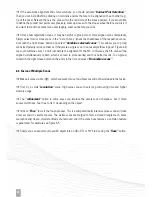
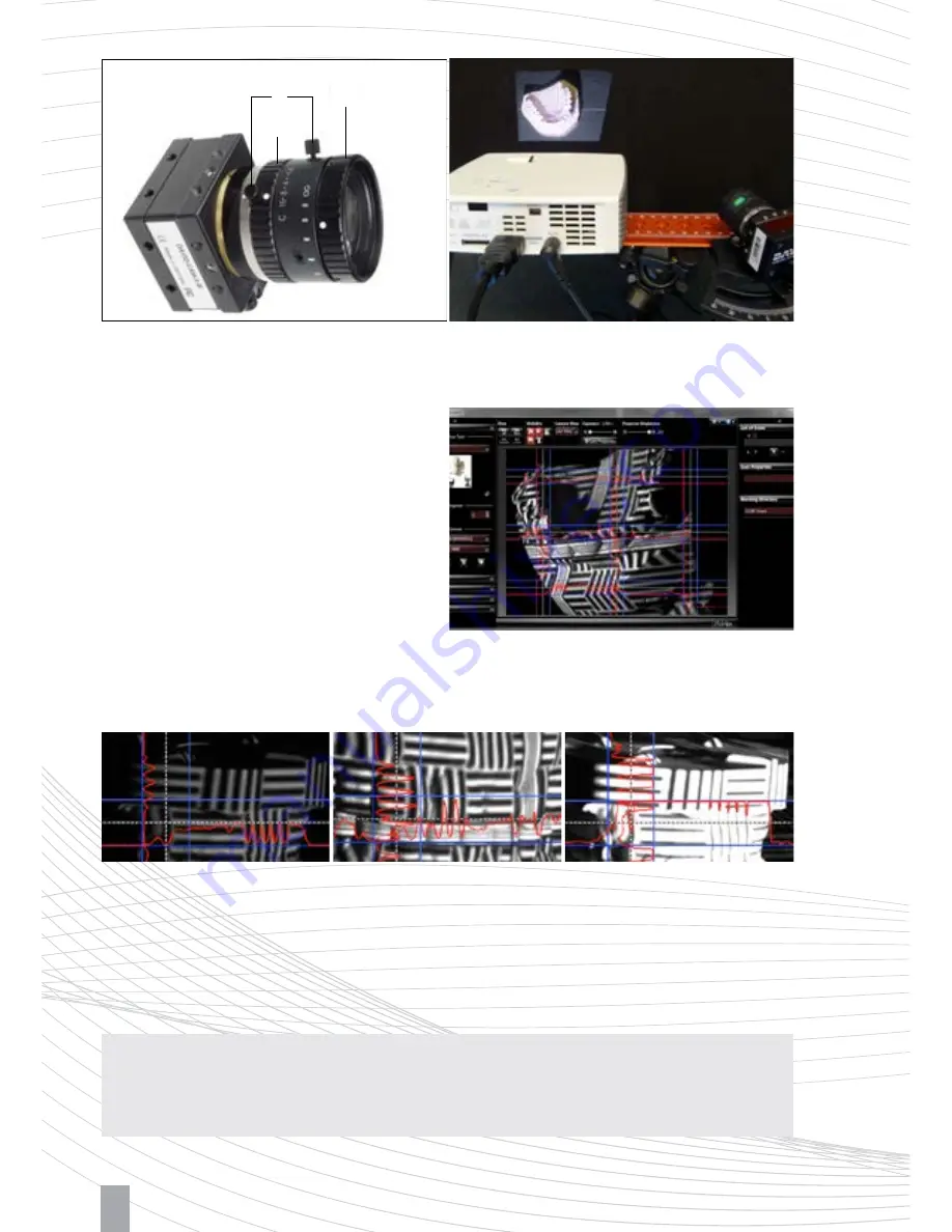
Figure 4.3: Setup of the object and arrangement of the projector
and camera
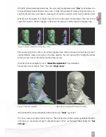
Figure 4.4: Typical live image with good setup and settings
Figure 4.5: Left: Too dark
Z
open aperture further; Middle: Well-controlled sine wave almost reaching the blue borders; Right: Too
bright, sine is cut-off (overdriven)
Z
close the aperture somewhat
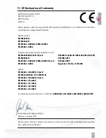
Figure 4.2: Adjusting rings (A) aperture and (B) focus,
(C) fixing screws
9
Camera brightness/aperture:
The ”Projector
Brightness“ slider in the software should be set
to maximum. You should only reduce it if a clean
modulation is not possible in the following.
Adjust the mechanical aperture (dial A). Consider
only those areas in the camera image which
show the regular waves! The displayed intensity
curves (red) must be sinusoidal and may neither
be undersaturated nor oversaturated, i.e. the red
sine curve (see Figure 4.4 and 4.5) should not be
cropped at the blue lines.
If the curves are strongly flattened in the dark area (bottom or left) without being close to the lower blue
lines, the ambient light may be too strong. In this case please darken the room.
Note:
The aperture dial (A) on the camera has a scale (f-stop from 16 to 1.4), see Figure 4.2. Even for
very bright conditions (small objects), please avoid setting f-stop higher than 16, otherwise you will lose
sharpness. If necessary, better reduce the value ”Projector Brightness“ in the software.
C
B
A
Summary of Contents for SLS-2
Page 1: ...QUICK GUIDE...