background image

45 


Status 

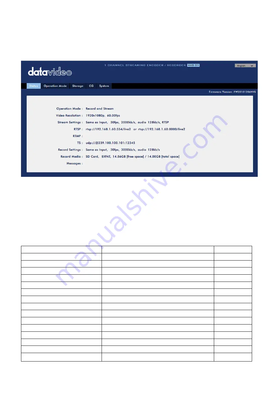
You will see the 

Status

 page immediately after logging into the NVS-31 web UI. On the Status page, 

you will be able to view the 

Operation Mode

Video Resolution

Stream Settings 

(RTSP/RTMP(S)/HLS/SRT/TS), 

Record Settings

Record Media

 and 

Messages

.  


Note: The NVS-31 web UI does not update automatically so to learn the latest device status, please 
refresh the page manually. 


While monitoring streaming and recording, please update the page periodically regardless of how you 
operate the device (using the device’s physical buttons only or using the device’s physical buttons 
along with the web UI). This ensures the page is always displaying the most up-to-date information.   

If an error occurs, the error code will be shown in the “

Messages

” field. The device’s error codes are 

listed in the table below. 

Error Messages 

Descriptions 

Error Code 

STR_UP_ETH_LINK_DOWN 

Ethernet Link Down 

133 

STR_UP_ETH_LINK_RESTORE 

Ethernet Link Up from Down 

134 

STR_UP_ETH_CONN_ERR 

RTMP Cannot Publish (Retrying) 

140 

STR_UP_ENC_START_ERR 

Encoder Start Failed 

129 

STR_UP_ENC_BUFF_ERR 

Encoder Buffer Error 

130 

STR_RUN_ETH_LINK_DOWN 

Ethernet Link Down (Dropped) 

133 

STR_RUN_ETH_CONN_ERR 

RTMP Drop Connection (Retrying) 

140 

STR_RUN_ENC_BUFF_ERR 

Encoder Buffer Error 

130 

STR_RUN_PROG_BUFF_ERR 

Streamer Buffer Error 

137 

STR_RUN_PROG_SOCKET_ERR 

Streamer Socket Error 

140 

STR_STOP_PROG_EXIT_ERR 

Streamer Stop Failed 

141 

REC_UP_DISK_ERR 

Disk Bad Sectors/Read Only/File System Error 

148 

REC_UP_DISK_EMPTY 

No Disk 

144 

REC_UP_ENC_START_ERR 

Encoder Start Failed 

129 

REC_UP_ENC_BUFF_ERR 

Encoder Buffer Error 

130 

Summary of Contents for HS-1600T

Page 1: ...4 CHANNEL HD SD HS 1600T HDBASET PORTABLE VIDEO STREAMING STUDIO Instruction Manual ...

Page 2: ...ROL PANEL 20 2 4 RECORD STREAM PANEL 21 CHAPTER 3 SWITCHER OSD MENU 23 3 1 START 23 Transition Type 23 Transition Speed 23 Wipe Effect 24 WIPE Border Size 24 WIPE Border Color 24 BKG Color 24 3 2 PIP SPLIT 24 PIP Source 25 PIP Size PIP Window Size 25 Position X 26 Position Y 26 Split Source 26 Border Size 26 Border Color 26 3 3 PIP CROP 26 3 4 LUMAKEY 27 Lumakey Source 27 Mode 27 Cleanup Level 27 ...

Page 3: ...HAPTER 5 APPLICATIONS 38 5 1 PLACING A LOGO ON THE VIDEO USING THE LUMAKEY FUNCTION 38 5 2 CONNECTING PTC 150T CAMERAS 38 CHAPTER 6 VIDEO STREAMING AND RECORDING 40 6 1 STREAMING NETWORK CONNECTION AND DEVICE SEARCH 40 Connecting to a DHCP Network DHCP Mode 40 Connecting to a NON DHCP Network Static IP 40 Default Fixed IP 41 Troubleshooting the Network Connection 41 Advanced Troubleshooting 44 6 2...

Page 4: ...CIFICATIONS 92 SERVICE AND SUPPORT 96 Disclaimer of Product Services The information offered in this instruction manual is intended as a guide only At all times Datavideo Technologies will try to give correct complete and suitable information However Datavideo Technologies cannot exclude that some information in this manual from time to time may not be correct or may be incomplete This manual may ...

Page 5: ...t should not be placed in a built in installation unless proper ventilation is provided 7 This product should only be operated from the type of power source indicated on the marking label of the AC adapter If you are not sure of the type of power available consult your Datavideo dealer or your local power company 8 Do not allow anything to rest on the power cord Do not locate this unit where the p...

Page 6: ...r under warranty The product warranty period begins on the purchase date If the purchase date is unknown the product warranty period begins on the thirtieth day after shipment from a Datavideo office All non Datavideo manufactured products product without Datavideo logo have only one year warranty from the date of purchase Damage caused by accident misuse unauthorized repairs sand grit or water is...

Page 7: ... collection point for the recycling of waste electrical and electronic equipment The separate collection and recycling of your waste equipment at the time of disposal will help to conserve natural resources and ensure that it is recycled in a manner that protects human health and the environment For more information about where you can drop off your waste equipment for recycling please contact you...

Page 8: ...he user to Pan Tilt and Zoom the PTC 150T camera In addition the HS 1600T also allows the user to adjust the PTC 150T s Focus IRIS and other settings HS 1600T also features an easy to use video streaming and recording device for professional video producers who need to simultaneously stream a live event and record the master quality version for post event editing 1 1 Features Full HD 1080P Video F...

Page 9: ...9 1 2 System Diagram ...

Page 10: ...l need to set the camera s baud rate to 38400 See Section 5 2 for setting the baud rate of connected cameras If the camera s baud rate is already pre set to 38400 the camera video should appear on the respective Multiview quadrants as soon as the camera is physically connected to the HDBaseT port Note The HDBaseT port is designed using Neutrik s etherCON A series connector system which is optimize...

Page 11: ...s Red and Green tally signals to each channel Red indicates On Air and Green indicates next camera source Tally output port can connect other Datavideo peripheral devices such as ITC 100 ITC 200 AM 100 or other monitor models allowing the peripheral device to communicate with the HS 1600T or send tally signal to be displayed on the monitor See Appendix 1 for physical pin connections and Section 3 ...

Page 12: ...t allows the user to establish direct connection between the notebook computer and the HS 1600T in order to access the built in NVS 31 or connect the NVS 31 to any local area network Note See the Chapter 6 Video Streaming for device configuration 2 2 Switcher Keyboard Panel Volume Control Program Preview Transition Control Switcher Settings PIP Keyer Transition Effects Camera Presets Focus IRS Whi...

Page 13: ...Balance Transition Control PAN TILT ZOOM T Bar manual transition Speed Selection Buttons CUT button Joystick PAN TILT AUTO transition button VR Knob ZOOM Program Preview LOCK Button Program row Camera MENU Control Preview row MENU Button ENTER Button Switcher Settings Menu browsing buttons Press the MENU button to gain access to the menu use the up down left right arrow buttons to browse through t...

Page 14: ...the control panel The Center WIPE can be selected from the menu Start Pressing the REV button reverses the direction of the WIPE MIX Enable Disable Button A MIX also known as a dissolve is a transition wherein the Program video is replaced by the Preview video at a smooth rate and at the same time Pressing the MIX button enables the MIX transition effect and automatically disables the WIPE button ...

Page 15: ... Keyer Enable Disable Buttons Luma Key PGM Shows the luma key source on the PGM output and enables the luma key effect however the luma key effect cannot be previewed on the QUAD split view display Luma Key PVW Enables luma key source for the PGM output on the next transition Holding down this button allows selection of the luma key source from the Preview Source row The selected source button wil...

Page 16: ...Pressing the Cut button performs immediate manual switch between PVW and PGM views without the transition effect AUTO Button Pressing the Auto button automatically transitions PVW and PGM views according to the selected speed and the configured transition effect Program Output Program Source Row Pressing the number buttons along the PROGRAM row selects a video source for the PGM view BKG button Pr...

Page 17: ...ssing the BLK button sets the Preview OUT to a black screen Volume Control Volume Adjustment Sliders Sliders to control audio levels for the Main audio mixer Headphone Volume Audio volume of the connected headphone Master Main audio output volume Headphone Jack Headphone jack accepts the mini jack plug of the stereo headphone type The headphone volume is controlled by the Headphone volume adjustme...

Page 18: ...llows the current camera position to be stored in a chosen Channel Preset Button by pressing the corresponding preset button Press again to exit STORE MODE FOCUS IRIS White Balance Focus Adjustment To manually control the FOCUS setting first press the MANUAL button to enter the manual mode The button LED will be turned ON to indicate that the manual mode is enabled The FOCUS dial can then be rotat...

Page 19: ...the joystick up or down to tilt the selected PTZ camera up or down Note Before attempting to use the joystick to PAN or TILT a selected camera first make sure the LOCK button is not enabled If the LOCK button LED is ON the joystick is locked press the LOCK button to unlock the joystick VR Knob ZOOM ZOOM Twist the joystick clockwise to the right or anti clockwise to the left to have the selected PT...

Page 20: ...E option on the OSD MENU to exit ENTER Button Press this button to select a menu option after the camera OSD menu is opened 2 3 Monitor Control Panel Power Switches the HS 1600T Monitor Power ON OFF BLUE Press this button to eliminate the red and green component of input signals Only the blue component of an input is displayed on the screen This allows adjustments of chroma and phase Phase adjustm...

Page 21: ...ature between zoom x1 x2 x4 and x8 Menu Navigation Buttons Display and navigate the setup menus See Monitor Menu Options for more details Aspect Ratio Button Sets the Aspect Ratio to 16 9 4 3 Volume Control Adjusts the speaker headphone volume up down MUTE Mutes the audio from the internal speakers or headphone socket 2 4 Record Stream Panel RECORD Press the RECORD button to start enable video rec...

Page 22: ...ow L bitrates for each of the RECORD STREAM and RECORD STREAM buttons See section 6 4 for details Note Not all models come with the bitrate button SD Card Slot Insert an SD card into the SD card slot for video recording Note that you should only use Class 10 SD card or above See the Appendix Recommended SD Cards for a list of SD cards recommended by Datavideo Note Do not remove SD card while it is...

Page 23: ... Effect 1 Horizontal 2 Vertical 3 Center 1 WIPE Border Size OFF Small Middle Large Small WIPE Border Color White Yellow Cyan Green Magenta Red Blue Black Red BKG Color White Yellow Cyan Green Magenta Red Blue Black White Transition Type The HS 1600T provides two types of transition effect which are cross dissolve MIX and WIPE The default setting is MIX Transition Speed The Transition Speed allows ...

Page 24: ... width large is the maximum wipe border width WIPE Border Color In this option you will be allowed to select a color for your wipe border The available colors are listed as follows White Yellow Cyan Green Magenta Red Blue Black BKG Color In this option you will be allowed to assign a color to the BKG button The available colors are listed as follows White Yellow Cyan Green Magenta Red Blue Black 3...

Page 25: ...l be allowed to assign the PIP source the available sources are listed as follows Black Input 1 Input 2 Input 3 Input 4 Background Color Bar Tip To quickly assign the PIP source simply press and hold the PIP PGM button and then select a source from the Program BUS PIP Size PIP Window Size The PIP window size ranges from 1 to 100 with 1 being the smallest and 100 being the largest Therefore 50 woul...

Page 26: ...rogram out view can be selected in this option The available split sources are listed as follows Black Input 1 Input 2 Input 3 Input 4 Background Color Bar Border Size The Border Size generally allows the user to select an appropriate PIP border width Setting the Border Size to OFF turns the PIP border off Setting the border size to small selects a thin border middle will yield a medium size width...

Page 27: ...y source will be the upper layer and the PIP source will be the lower layer The layer order cannot be changed Main Sub Menu Options or Values Default Value Lumakey Lumakey Source Black Input 1 Input 2 Input 3 Input 4 Background Color Bar Input 2 Mode Black White Black Cleanup Level 0 100 20 Transparency 0 64 64 Lumakey Source Lumakey source is where you can select the image for luma keying The ava...

Page 28: ... allows the user to assign the HDMI audio channel The default audio channel pair is Channel 1 2 You can select any of the four audio channel pairs Level There are two different audio standards available for selection The user can either select the EBU or SMPTE standard By selecting AUTO allows the device to automatically detect the audio standard When the image is 50 Hz the audio follows EBU stand...

Page 29: ...ose previously saved User configurations Use the SHIFT button to switch between USER MEMORY 1 3 and USER MEMORY 4 6 Save Memory Use the up down arrow to select the desired memory location and save the current setting by selecting Save Factory Default Reset Once selected the factory default settings will be restored The device will start the factory reset process in 2 to 3 seconds after Reset is se...

Page 30: ... to select an appropriate PROGRAM output resolution The available resolutions are listed as follows 1080p 60 1080p 59 94 1080p 50 1080p 30 1080p 25 1080i 60 1080i 59 94 1080i 50 720p 60 720p 59 94 720p 50 576i 480i Once done simply go to Save Setup to confirm the selected output resolution Note Please make sure input and output resolutions are identical to avoid unexpected errors MV Out Res In MV ...

Page 31: ...422 Save Setup In this option select Save to save the current configuration Language The available OSD menu languages are English Traditional Chinese and Simplified Chinese MB and KBD Software The MB and KBD software fields display the respective version numbers 3 8 Camera In the Camera menu the user will be able to change the camera name view camera information and perform some basic camera setti...

Page 32: ...PGA Version Motor Version and DVIP Version Video In the Video sub option you will be able to configure the Video Format Mirror Mode Joystick Direction and Joystick Speed The available resolutions in Video Format are listed as follows 1080i 60 50 1080p 59 94 50 29 97 25 720p 59 94 50 In Mirror Mode there are three types of modes available V Vertical mirroring H Horizontal mirroring H V Horizontal a...

Page 33: ...selected camera select Standby to enter the camera into power standby mode R Gain B Gain The red and blue components can be adjusted ranging from 0 to 255 Tally LED You can either turn the tally light off or enable the red or green tally light ...

Page 34: ...chosen setting has been confirmed with the ENTER button it is stored within the switcher s non volatile memory 4 1 MENU Options Main Options Sub Options Values Values MAIN ADJUST BRIGHTNESS 0 100 CONTRAST 0 100 SHARPNESS 0 100 SATURATION 0 100 TINT 0 100 BACKLIGHT 0 100 NR HIGH MID LOW OFF DLC ENABLE DISABLE VOLUME 0 100 EXIT COLOR 6500 9300 7500 USER COLOR RED 0 100 GREEN 0 100 BLUE 0 100 EXIT SC...

Page 35: ...uttons to change the value and then press Enter to store the new value and return to the main menu To configure other settings such as Contrast Saturation Sharpness TINT and etc use the Up Down buttons to select the desired option Follow the above procedure to set the new value COLOR Press ENTER to access the COLOR menu and the first option will be highlighted Press ENTER to select the first color...

Page 36: ... return to factory defaults 4 2 Firmware Update Procedure Monitor From time to time Datavideo may release new firmware to either add new features or to fix reported bugs in the current HS 1600T Monitor firmware Customers can update the firmware themselves if they wish or they can contact their local dealer or reseller for assistance should they prefer this method This section describes the firmwar...

Page 37: ...in 4 Plug the USB 2 0 pen drive into the USB 2 0 port labelled MONITOR F W UPGRADE on the front of the monitor button panel 5 Reboot HS 1600T and the update will start automatically 6 The HS 1600T Monitor will reboot itself at the end of the process Note The USB port can also be used to power the connected USB LED light ...

Page 38: ... 5 Set the Cleanup Level to 10 if the background is in total black 6 Transparency is set to 64 if an opaque logo is desired Opaque logo can be created by setting the Transparency to 64 Semi transparency effect can be generated by setting the Transparency to a value between 0 and 64 7 Exit the menu after the Logo is properly configured 8 Press the Luma Key PGM button to place the logo on the Progra...

Page 39: ...onfigure the DVIP port REMOTE CONTROL 1 PAN TILT REVERSE P T 2 REMOTE SOURCE DVIP SW 3 SET RS422 4 SET DVIP 5 SET IR 6 PTZ INFO OUTPUT OFF 7 ESCAPE 6 Set the DVIP baud to 38400 SET DVIP 1 DVIP BAUDRATE 38400 2 ESCAPE 7 Connect the PTC 150T to the HS 1600T which should automatically assign an IP to the PTC 150T ...

Page 40: ...acquire the NVS 31 s IP address Connecting to a DHCP Network DHCP Mode Follow the following procedure to scan your DHCP network for connected NVS 31 devices Note The NVS 31 will be automatically assigned an IP address upon connection to the DHCP network 1 Connect the NVS 31 s stream port to the network via an Ethernet cable 2 Turn on the HS 1600T s power and the NVS 31 will also be turned ON in th...

Page 41: ...o the following to reset the network settings Turn off the switcher Press the RECORD and STREAM buttons at the same time then turn ON the power of the switcher Wait for about five seconds and release the button push as soon as you see the RECORD and STREAM button LEDs light up The IP address should be the default IP which is 192 168 1 30 Troubleshooting the Network Connection Connect the NVS 31 to...

Page 42: ...irectly using an Ethernet cable not necessarily a crossover cable Next change the network settings of your PC or laptop Click START located at the bottom left corner of your screen On the text bar enter Network Connections then click the icon that appears Double click the network adapter that connects your PC or laptop to the network Click the Properties button Select Internet Protocol Version 4 T...

Page 43: ...tatic IP and default gateway Make sure that the default gateway matches your connected network and no device shares the same IP as the NVS 31 For example if your router s default gateway IP is 10 10 1 1 then in the default gateway field you should also enter 10 10 1 1 Then set the IP address of the NVS 31 to 10 10 1 X which can range from 10 10 1 2 to 10 10 1 255 Pick an unused IP address DHCP Dis...

Page 44: ...dress the device s MAC address is on the print label at the bottom of your HS switcher MAC address starts with 00 07 36 03 xx xx Switcher s MAC address starts with 00 07 36 07 xx xx HS 1600T and HS 1600T only On the command prompt terminal on MAC OS enter arp a then press enter key to display an ARP list See if the NVS 31 is successfully connected to the network Execute services msc and on the rig...

Page 45: ...occurs the error code will be shown in the Messages field The device s error codes are listed in the table below Error Messages Descriptions Error Code STR_UP_ETH_LINK_DOWN Ethernet Link Down 133 STR_UP_ETH_LINK_RESTORE Ethernet Link Up from Down 134 STR_UP_ETH_CONN_ERR RTMP Cannot Publish Retrying 140 STR_UP_ENC_START_ERR Encoder Start Failed 129 STR_UP_ENC_BUFF_ERR Encoder Buffer Error 130 STR_R...

Page 46: ..._EXIT_ERR Unmount Disk Failed 156 REC_STOP_PROG_EXIT_ERR Recorder Stop Failed 157 Operation Mode Click the Operation Mode tab on the tool bar to open the operation mode configuration page The NVS 31 offers the following operation modes Record and Stream Streaming and recording functions are enabled at the same time Stream Only Only streaming mode is enabled Record Only Only recording mode is enabl...

Page 47: ...pes are available on the NVS 31 and they are RTSP RTMP S HLS SRT and TS See Section 6 3 for details Click the Apply button to apply the new stream settings Click the Start button to open the stream and the Stop button to end the stream As for recording the settings are Resolution Frame Rate Profile Video Bitrate bps Audio Bitrate bps GOP File Name and File Size ...

Page 48: ...48 Click the Apply button to apply the new record settings Click the Start button to start recording and the Stop button to stop recording ...

Page 49: ...to either match your original video source or scale it down For example capture at HD 720 and stream at HD 720 Or capture at HD 720 and stream at 540 high You should never be scaling up and streaming at a higher resolution than your original video source For example it does not make sense to capture at 720 and stream at 1080 Note that you will also have no gain in quality and you are using more ba...

Page 50: ...able upload bandwidth capacity on a DEDICATED line For example if the result you get from a speed test shows that you have 2Mbps of upload speed available your combined audio and video bitrate should not exceed 1Mbps Usually high bitrate means good image quality however there are also exceptions For example SD video may appear acceptable at 1000 Kbps 1M but HD video is unacceptable at 1000 Kbps Th...

Page 51: ...itrates consume more bandwidth across the IP network In a gigabit office LAN high bitrate may not be a concern and Speed Bandwidth is therefore not a limitation in an NVS 31 application environment If your available bandwidth is limited you should reduce both your resolution and your bitrate accordingly A good rule of thumb is for the bitrate of your stream to use no more than 50 of your available...

Page 52: ...RTMP Publish only and not RTMP Local Stream Name Enter the stream name or key from any live streaming platform such as Ustream Account Enter your RTMP account name Password Enter the password of your RTMP account Audio Only In this option the user is allowed to choose to stream Audio Only or Video Only If disabled video and audio streams will be delivered simultaneously Stream Type TS TS Port The ...

Page 53: ... This means that greater amounts of detail can be expressed in the image but larger files sizes and a greater amount of storage i e hard drive space are required to save the images or video Frame Rate Frame rate greatly impacts the style and viewing experience of a video Different frame rates yield different viewing experiences and choosing a frame rate often means choosing between things such as ...

Page 54: ...es the best image quality and is suitable in most instances Video Bitrate bps The bitrate of the video specifies the amount of information stored in the video The higher the bitrate is the clearer the video is Recommended video bitrate 720P or lower 8 10 mbps 1080P or higher 15 mbps or higher Audio Bitrate bps The NVS 31 offers the user the following audio bitrates at which you may want to record ...

Page 55: ...ile that is currently being recorded Note The record function is activated after the Start button is clicked The REC indicator will appear as shown on the left Flashing indicates that the record function is starting A solid color indicator means the record function has been activated successfully The indicator flashing three times then turned off indicates errors The activation time is approximate...

Page 56: ...mended SD Cards for a list of SD cards recommended by Datavideo Product Display of the name of the SD card Capacity Display of the SD card s total capacity and the remaining capacity Storage Format Select a storage format before clicking to format your SD card FAT32 EXFAT NTFS Storage Content Display of the SD card content File name Last Modified Size Type ...

Page 57: ...e CG settings on the CG page are shown in the diagram below CG Settings CG Enable Disable Select ON OFF from this drop down menu to enable disable the CG overlay function Text Enter the text of the CG overlay Location X Enter the x coordinate Location Y Enter the y coordinate Background You can either select a black background or none ...

Page 58: ...lows the user to configure several network and system related settings such as DHCP enable disable static IP address subnet mask default gateway primary and secondary DNS and etc The system settings are HLS preview enable disable time settings firmware update device name and account login information The system page is shown in the diagram below ...

Page 59: ...59 ...

Page 60: ...buttons simultaneously Approximately after 5 seconds release the RECORD and STREAM buttons as soon as the button LEDs are turned ON Fixed IP address is 192 168 1 60 by default Subnet Mask Static IP address mode requires subnet mask which is 255 255 255 0 by default Default Gateway Static IP address mode requires default gateway which is 192 168 1 254 by default Primary DNS Optional Primary DNS is ...

Page 61: ...op down menu you can either select to allow the device to retrieve the time automatically from the Network Time Protocol NTP server or manually select a time zone from the Time Zone drop down menu Time Zone Click the drop down menu to select a time zone for your device Date Time Date and Time fields show the device s system date and time values ...

Page 62: ...e PC s hard disk Click the Update button after the latest firmware file is uploaded Device Name Setting Device Name Setting Enter a name for this device and click the Submit button to write this name into the device Account Setup Account Setup Enter the NVS 31 s account name and password Click the Apply button to save the new settings System Control Restore to Default Click this button to restore ...

Page 63: ...pair page and click the File List drop down menu to select the damaged MP4 file 2 If the MP4 file can be repaired you will see a pop up dialogue box prompting MP4_FIX_OK click OK then the Submit button Note If the selected MP4 file cannot be repaired a dialogue box prompting MP4_FIX_ERROR_MDATA will pop up 3 The file is repaired when you see a dialogue box prompting File repair finish Click OK and...

Page 64: ...ttings of these options and how to stream your video using these methods RTSP TS HLS SRT In the RTSP TS HLS SRT modes the NVS 31 is a stream server which allows any client device to connect and playback your video stream However if you would like to stream to multiple client devices we recommend using a separate media server to set up your streaming environment The following operation procedure us...

Page 65: ...ate the RTSP URL 4 Based on your settings the device will automatically generate the RTSP URL 5 Before streaming the video via RTSP enter the RTSP URL into the client device 6 Open VLC then click Open Network Stream shown in the diagram below 7 As shown in the diagram below enter the stream URL then click Play to start streaming ...

Page 66: ...t number which is 12345 by default 4 In the TS IP field enter your PC s IP address such as 192 168 1 66 5 Click the Start button to generate the TS URL which in this example will be udp 192 168 1 66 12345 as shown in the diagram below 6 Before streaming the video via TS enter the TS URL into the client device ...

Page 67: ...wn in the diagram below 8 As shown in the diagram below enter the stream URL then click Play to start streaming Follow the steps below to obtain the HLS URL 1 Open the stream settings page 2 Select HLS 3 Click the Start button to generate the HLS URL ...

Page 68: ... a m3u8 stream URL as shown below 5 Before streaming the video via HLS enter the HLS URL into the client device 6 Open VLC then click Open Network Stream shown in the diagram below 7 As shown in the diagram below enter the stream URL then click Play to start streaming ...

Page 69: ...t Edge to open the m3u8 stream URL Follow the steps below to obtain the SRT URL 1 Open the stream settings page 2 Select SRT and the SRT port number is 9001 by default 3 Click the Start button to generate the SRT URL 4 Before streaming the video via SRT enter the SRT URL into the client device 5 Open VLC then click Open Network Stream shown in the diagram below ...

Page 70: ...RTMP S mode the NVS 31 can only send one data stream to one CDN or media server that supports the Real Time Messaging Protocol or the Real Time Messaging Protocol over an TLS SSL connection Examples of the RTMP S media server are USTREAM and Youtube Note The NVS 31 supports RTMP only and not the RTMP local ...

Page 71: ...be Live Dashboard https www youtube com live_dashboard 3 On the left column locate and click Stream now 4 On the right scroll down to the bottom where you will be able to find Server URL and Stream name key 5 On the NVS 31 open the Stream Only operation mode page 6 Select RTMP from the Stream Type drop down menu 7 Enter the Server URL rtmp a rtmp youtube com live2 obtained from the Youtube Live St...

Page 72: ...generated 11 The RTMP URL is another alternative that allows you to view the live stream on a web browser Enter the RTMP URL into the web browser s address bar then hit the Enter button to open the live video stream 12 Click the Stop Stream button to stop live streaming Tip You are allowed to stream audio or video only Text Overlay Video The HS 1600T s built in video streaming server not only allo...

Page 73: ... the front panel of the HS 1600T give the user certain controls of the record and stream functions In this section we will cover operations of these two buttons in detail Button LED behaviors and their corresponding states are listed in the table below RECORD Button STREAM Button Solid White Record function in idle state Stream function in idle state Blinking Red Record function is activating or r...

Page 74: ...ted Note The STREAM button is disabled in the Record Only mode Stop streaming While streaming the STREAM button is solid red Press and hold the STREAM button for approximately 2 seconds When the stream function is terminating the STREAM button turns from solid red then blinking red and finally to solid white When the STREAM button is solid white this indicates that the stream function has been suc...

Page 75: ...lid white Simultaneously press and hold the RECORD and STREAM buttons for more than 1 second but less than 3 seconds The button LED should behave according to the device s next operation mode The LED behaviors are summarized in the table below Solid red RECORD button Solid white RECORD button Solid red STREAM button Stream Record Stream Only Mode Solid white STREAM button Record Only Mode None The...

Page 76: ...ed Press and hold the RECORD button for approximately 2 seconds When the record function is terminating the RECORD button turns from solid red then blinking red and finally to solid white When the RECORD button is solid white this indicates that the record function has been successfully terminated Stream Button Press the STREAM button to start stop streaming Start streaming When idle the STREAM bu...

Page 77: ...ECORD STREAM button is solid white this indicates that the record and stream functions have been successfully terminated Bitrate Button Follow the steps below to switch the stream bitrate mode using the BITRATE button Press and hold one of the RECORD STREAM RECORD and STREAM buttons until the pressed button starts blinking red Continue holding down one of the RECORD STREAM RECORD and STREAM button...

Page 78: ...lid white Simultaneously press and hold the RECORD and STREAM buttons for more than 1 second but less than 3 seconds The button LED should behave according to the device s next operation mode The LED behaviors are summarized in the table below Solid red RECORD button Solid white RECORD button Solid red STREAM button Stream Record Stream Only Mode Solid white STREAM button Record Only Mode None The...

Page 79: ...aining new features or reported bug fixes from time to time This section outlines the firmware upgrade process which should take approximately 10 minutes to complete 1 Visit the official product page https www datavideo com tw product HS 1600T where you can download the latest firmware file 2 Login the NVS 31 web interface then click the System tab to open the system configuration page 3 Scroll do...

Page 80: ... buttons simultaneously release them when the two buttons start flashing red The NVS 31 starts erasing the previous update files and uses the previously uploaded file to force the firmware update The firmware update is complete when the RECORD and STREAM buttons turn solid white Formatting the SD Card You are also allowed to format the SD card on the HS 1600T Follow the steps below to format your ...

Page 81: ...ollector output Tally output of input video Program 1 2 No Function 3 Preview 1 Open collector output Tally output of input video Preview 1 4 RCOM GND Ground Ground 5 Program 4 Open collector output Tally output of input video Program 4 6 Program 2 Open collector output Tally output of input video Program 2 7 No Function 8 Preview 2 Open collector output Tally output of input video Preview 2 9 GND...

Page 82: ... Update Procedure 1 On the PC copy the two HS 1600T firmware binary files to the root directory of a USB thumb drive After the files are successfully copied safely remove the USB thumb drive from the PC HS 1600T bin The HS 1600T Keyboard KB Firmware is approximately 27KB and usually with a version number of V1 X HS 1600TM bin The firmware file for the HS 1600T Mainboard MB and OSD MENU fonts is ap...

Page 83: ...600T startup screen 6 The OSD fonts will be automatically updated after the Step 5 is executed and the update status will be indicated by the LED color green of the preview row buttons The machine reboots itself after the mainboard is updated and the BLK button will start flashing green after the reboot The OSD fonts update will start approximately 10 seconds after the mainboard finishes booting T...

Page 84: ... is renamed to MSTFLASH bin 4 Plug the USB 2 0 pen drive into the USB 2 0 port labelled MONITOR F W UPGRADE on the front of the monitor button panel 5 Reboot HS 1600T and the update will start automatically 6 The HS 1600T Monitor will reboot itself at the end of the process Note The USB port can also be used to power the connected USB LED light Video Streaming Server To update the video streaming ...

Page 85: ...to the NVS 31 5 After the file has been successfully uploaded you will see a file upload success message Click the Update button to start the firmware update process 6 The device will reboot itself after it is updated successfully Note If the device is recording or streaming you must turn them off before initiating the firmware update ...

Page 86: ...endix you will find a list of SD cards recommended by Datavideo Recommended SD Cards No Brand Model Pictures 1 Kingston SDHC I C10 16G 2 SANDISK Extreme SDXC I C10 U3 V30 64GB 3 SONY SDXC I C10 U1 64GB 4 SANDISK Extreme PRO SDXC I C10 U3 128GB 5 SONY SDXC I C10 U3 64GB 6 TOSHIBA SDHC C10 16GB ...

Page 87: ...87 Recommended SD Cards No Brand Model Pictures 7 SANDISK Extreme SDHC C10 16GB 8 ADATA Premier Pro microSDXC I UHS I U3 Class 10 with SD adapter 64GB 9 SANDISK ULTRA SDHC SDXC UHS I 128 GB ...

Page 88: ...downloaded from the SD association s official website https www sdcard org cht downloads formatter_ 4 index html b In this case why doesn t the system issue any error messages upon start of video recording b The system only detects and sets write speed upon start of video recording The system will not issue an error message if insufficient write speed is experienced while video recording is in pro...

Page 89: ...B Use separate patch and equipment cords in the first 20 meters C Avoid use of tie wraps D Use horizontal wire management techniques For example route odd ports to upper management and even ports to lower management E Loosely place cables in vertical wire management F Reduce maximum conduit fill density to 40 G It is recommended to roll the cable around a fixed radius drum in an orderly manner Thi...

Page 90: ...t ethernet cable due to following reasons A There is no twisted paired inside the flat ethernet cable to offset the interference B There is no cross spacer between the cables inside the flat ethernet cable C The diameter of each core cannot meet the AWG standard due to cut corners For the CAT5e cable the diameter for most of the flat Ethernet cables cannot meet the 24AWG 0 49 0 51mm standard and t...

Page 91: ...91 Appendix 6 Dimensions All measurements in millimeters mm ...

Page 92: ... 1 x STREAM RJ 45 Audio Input 2 x Balanced XLR 1 x Stereo RCA L R De embedded Digital Audio Audio Output 1x Stereo headphone Embedded Audio Support 2 CH Audio embedded Audio Delay Calibration N A A V Switching N A USK 1x USK Lumakey support DSK N A Picture in Picture 1 Logo Insertion N A Built in Audio Mixer Yes Built in Monitor Display 17 3 HD TFT LED backlit 1920x1080 pixels Built in Intercom Ta...

Page 93: ...TCP UDP RTSP Elementary Streaming RTMP Publish Streaming Control Web browser UI for configuration and control Socket commands Recording File System FAT exFAT NTFS Recording File Format MP4 Recording Setting Control Web UI for system configuration and control Dimensions LxWxH 455 x 355 x 134 mm Weight 17 2 Lbs 7 8 Kg Reinforce Plastic Case Accessory CB 60 61 62 ...

Page 94: ...94 Notes ...

Page 95: ...95 Notes ...

Page 96: ...Jun 12 2020 Version E7 Datavideo Technologies Co Ltd All rights reserved 2020 www datavideo com product HS 1600T ...

Reviews: