background image

32 


4.7  AUX Lumakey 

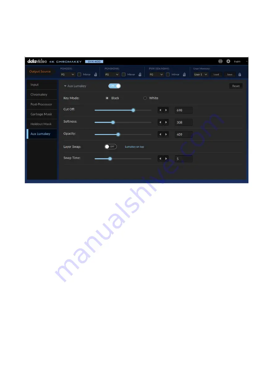
The “AUX Lumakey” performs lumakey on the input source from the AUX interface. Various 
parameters of the AUX lumakey will be described in this section.   


First enable the AUX Lumakey then adjust the following parameters. To reset the parameters, simply 
click the Reset button.  

Key Mode 
Select “Black” if the foreground is shot against a black background and “White” if the foreground is shot 
against a white background.  

Cut Off 
The default “Cut Off” value is 0. Increase this value gradually until either of the black and white 
backgrounds of the AUX source is 100% removed. For a black background, set Cut Off to 10-20% of its 
maximum value. For a white background, set Cut Off to 80-90% of its maximum value.  

Softness 
It allows users to determine the softness of the edge of the foreground subject. Increase this value 
if you would like a gradient edge effect for the foreground subject.  Please note that setting 
softness to a high value may cause the foreground subject to become semi-transparent.  

Opacity 
Opacity sets the transparency of the foreground subject. Setting it to 1000 will make the 
foreground subject transparent and a zero value means fully opaque.  

Layer Swap 
Enable “Layer Swap” to place the chromakey layer on top of the AUX Lumakey layer and vice versa.  

Swap Time 
Swap time sets the transition time during layer swap. For example, if the swap time is set to 20, 
multiply this number by 0.1 to derive the transition time of 2 seconds.    

Summary of Contents for DVK-400

Page 1: ...DVK 400 4K CHROMAKEY Instruction Manual...

Page 2: ...SIC SETUP 11 3 1 DVIP CONNECTION 11 3 2 RS 232 INTERFACE 15 CHAPTER 4 USER INTERFACE 17 4 1 OUTPUT SOURCE 17 PGM SDI 17 PGM HDMI 18 PVW SDI HDMI 18 User Memory 19 4 2 INPUT 19 4 3 CHROMAKEY 21 Matte G...

Page 3: ...ill try to give correct complete and suitable information However Datavideo Technologies cannot exclude that some information in this manual from time to time may not be correct or may be incomplete T...

Page 4: ...ly be operated from the type of power source indicated on the marking label of the AC adapter If you are not sure of the type of power available consult your Datavideo dealer or your local power compa...

Page 5: ...cident misuse unauthorized repairs sand grit or water is not covered under warranty Viruses and malware infections on the computer systems are not covered under warranty Any errors that are caused by...

Page 6: ...nserve natural resources and ensure that it is recycled in a manner that protects human health and the environment For more information about where you can drop off your waste equipment for recycling...

Page 7: ...d 10 bit color depth Easy operation and control via LAN connection to a Notebook PC Advanced algorithm for presenting transparency smoke reflection and shadow in detail Easy to use Spill Suppression f...

Page 8: ...8 1 2 System Diagram...

Page 9: ...cket connects the supplied 12V PSU DC IN 12V POWER Switch Make sure this power switch is turned ON before pressing the power button on the front panel Grounding Terminal When connecting this unit to a...

Page 10: ...w and PVW is preview RS 232 REMOTE CONTROL Use an RS 232 to USB adapter cable to connect your laptop to the device directly for remote control DVIP The DVIP port allows the user to control DVK 400 on...

Page 11: ...low the steps outlined in the subsequent sections to establish direct connection to your DVK 400 3 1 DVIP Connection DVIP is a network control protocol developed by Datavideo to facilitate connection...

Page 12: ...12 3 Open the DVK 400 User Interface then at the top right corner of the interface click the Globe icon...

Page 13: ...laptop s Ethernet card from the EtherNetCard drop down menu which is 192 168 100 5 in this example If this is your first time using the device click the Scan button on the right of the EtherNetCard d...

Page 14: ...ck the Connect button to start connecting to the device As soon as the connection to the device has been established successfully you will see the message Connected shown in yellow after which the Con...

Page 15: ...below to establish direct connection to the device from a laptop or PC via RS 232 1 Use an RS 232 to USB adapter cable to directly connect your laptop to the DVK 400 2 Open the DVK 400 User Interface...

Page 16: ...evice s corresponding COM port which is COM7 in this example 5 Click the Connect button to establish connection Note In case of connection failure check that the cable is properly connected and the la...

Page 17: ...anel Controller to control DVK 400 See the TPC 700 user manual for setup instructions 4 1 Output Source The Output Source row located at the very top of the UI allows you to configure the video source...

Page 18: ...p down menu allows you to select one of the following video sources for the PGM HDMI OUT port FG FOREGROUND CAMERA video source BG BACKGROUND video source AUX Video source connected to the AUX port Ma...

Page 19: ...e Mirror checkbox flips the output image along the vertical axis 2 Click the lock icon locks the output port thus disabling video source selection User Memory The User Memory function allows the user...

Page 20: ...be frozen At this time you can remove the input source of the frozen screen without affecting the display of the output screen Note If the DVK 400 is turned off the frozen screen will be removed this...

Page 21: ...21 4 3 Chromakey In this section we will show you how you can adjust the chromakey settings which involve the following Matte Generation Dark Enhancement...

Page 22: ...22 Bright Enhancement Shadow Enhancement Spill Suppression Edge Fix HD only...

Page 23: ...The DVK 400 then calculates the optimal screen color adjusts the chromakey parameters accordingly and finally applies the key to the foreground This entire process should take approximately 2 seconds...

Page 24: ...W OUT to Matte see Section 4 1 Output Source for a clearer view of the process You can use the slider or left and right arrow keys to adjust the Black Level White Level Adjust the white level to obtai...

Page 25: ...d right arrow keys to adjust the Bright Level Click Reset to return to the default value Shadow Enhancement Turning ON this option enables Shadow Enhancement Shadow Enhancement Under certain circumsta...

Page 26: ...ion range is 400 700 The default value is 500 You can use the slider or left and right arrow keys to adjust the Spill Suppression Spill Balance If the Spill Balance value is increased the skin tone wi...

Page 27: ...to 0 0 5 0 pixel horizontal shrinking unit 0 1 pixel You can use the slider or left and right arrow keys to adjust the Shrink Left Shrink Right The adjusting range for the Shrink Right is 0 50 which...

Page 28: ...bject Use the slider or left and right arrow keys to change the respective values To reset simply click the Reset button FG Corrector Enable FG Corrector to perform RGB color calibration for the foreg...

Page 29: ...riginal background within the set blur time To reset simply click the Reset button The default blur value is 50 and the default blur time is 5 4 5 Garbage Mask After you apply a key you may need to cr...

Page 30: ...hown below The Border value ranges from 0 to 100 Use the slider or left and right arrow keys to change the value Invert when turned ON reverses the default garbage mask swapping its opaque and transpa...

Page 31: ...tom edges using the respective sliders or the left and right arrow keys Border allows you to soften the mask edges Increasing the border value creates round soft gradient edges as shown below The Bord...

Page 32: ...of its maximum value For a white background set Cut Off to 80 90 of its maximum value Softness It allows users to determine the softness of the edge of the foreground subject Increase this value if y...

Page 33: ...ion is set to ON the Output Resolution will be locked to show the format which is adjusted automatically according to current Foreground resolution and it can not be adjusted by user If the Factory De...

Page 34: ...own menu The available options are RGB444 YUV444 and YUV442 FW Version Firmware version is shown in this field FPGA Version FPGA Version is shown in this field Bootloader Version Bootloader version is...

Page 35: ...set to Factory Defaults Follow the steps below to reset the DVK 400 to Factory Default Settings 1 Click the Factory Default button 2 Click the Reset button to reset the DVK 400 to Factory Default Sett...

Page 36: ...o chromakeying garbage and holdout masks and AUX lumakey 5 1 Video Chromakeying First set up your device according to hardware setup instructions described in Chapter 3 Then follow the steps outlined...

Page 37: ...t the key color See Section 4 3 Chromakey for more information about key generation 5 After the foreground is chromakeyed switch your output to the MATTE view shown below 6 Fine tune the parameters bl...

Page 38: ...the Setup window by clicking the gear icon at the top right corner of the UI then set the output resolution to the resolution of the foreground camera Click the Save button after that 8 Run the backgr...

Page 39: ...that cannot be keyed such as 1 the screen edge 2 lighting stands that appear in the background and 3 uneven distribution of light Using the Garbage Mask tool you can create a garbage mask that removes...

Page 40: ...on purpose In the red rectangle at the bottom left corner of the diagram below because of uneven distribution of light the mask edge is vaguely seen To remove mask edges entirely from the composite vi...

Page 41: ...over the green area of the image that should be kept To understand how the holdout mask works you need to first understand the layer order on the DVK 400 shown in the diagram below The holdout mask si...

Page 42: ...pictures and the title of the slide shown against a green rectangle at the bottom left corner of the TV are incorrectly removed after chromakey is applied If left uncorrected the background image will...

Page 43: ...43 4 In the following image green components of the TV are kept after chromakey is applied...

Page 44: ...he foreground image such as 1 the screen edges 2 a lighting stand and 3 green components in the TV image To solve these issues we will need a garbage mask to remove the screen edges and the light stan...

Page 45: ...45 After you ve defined the garbage and holdout masks you will see the chromakeyed foreground overlapped on the background with the desired effects shown in the diagram below 1 2...

Page 46: ...and the green screen 2 can be chromakeyed with a reversed holdout mask After a chromakey is applied to the foreground the background should show through the green screen only First enable garbage and...

Page 47: ...shown below Apply the chromakey to the foreground image then set the output source to COMP on one of the output monitors you should see a combined view of the chromakeyed foreground and the backgroun...

Page 48: ...transition Please note that the fade transition time can be predetermined by setting the Swap Time Example 1 The diagram below illustrates a teaching scene The Earth is the AUX Lumakey layer and the t...

Page 49: ...ves the hand away from the simulated 3D Earth turn ON the Layer Swap to move the Chromakey layer on top of the AUX Lumakey When the teacher walks to the Earth it would look as if the teacher walks to...

Page 50: ...makey layer and the teacher is the chromakeyed foreground With the Layer Swap enabled the Chromakey layer is above the AUX Lumakey layer therefore it looks as if the teacher is moving in front of the...

Page 51: ...51 Now when the teacher walks to the lectern it would then seem as if she walks to the back of the lectern as shown in the diagram below...

Page 52: ...he latest DVK 400 firmware from the Datavideo official website www datavideo com 2 Unzip the downloaded firmware files DVK400FW bin DVK400FP bin to the root directory of a USB thumb drive Note Make su...

Page 53: ...DVK 400 Level A Level B DL and Level B DS are supported on the DVK 400 5 Why is BG status on the Input page of the UI always showing 2160p29 even though the MAC PC connected to the BACKGROUND port has...

Page 54: ...hat the active signal resolution being 3840 x 2160 with a refresh rate of 29 Hz To modify the resolution click Display adapter properties for Display 2 3 On the Display Adapter Properties window that...

Page 55: ...window click Apply 6 Click Keep Changes to save the change 7 You should now see the Active signal resolution and the Refresh rate Hz changed to 1920 x 1080 and 59 Hz respectively and DVK 400 s BG Inp...

Page 56: ...round brightness yielding a more natural look of the smoke as shown below Background brightness set to 99 of the maximum brightness Foreground brightness set to 70 83 of the maximum brightness thus lo...

Page 57: ...57 Appendix 3 Dimensions Unit mm...

Page 58: ...G 6G 3G SDI Camera Loop Out AUX Input 1 x HDMI 1 4 Lumakey Overlay External Matte or Camera Video Output 1 x 12G 6G 3G SDI 1 x HDMI 2 0 Video PVW Output 1 x 12G 6G 3G SDI 1 x HDMI 2 0 Keying Options C...

Page 59: ...59 Note...

Page 60: ...Apr 26 2021 Version E9 Datavideo Technologies Co Ltd All rights reserved 2020 https www datavideo com product DVK 400...

Reviews: