


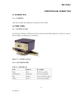


2-3
001-4006-101
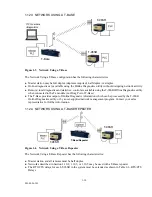
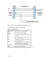
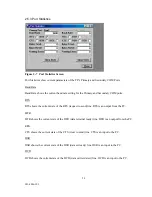
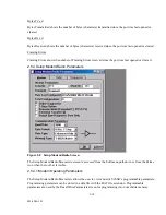
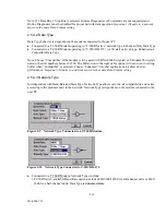
Figure 2-3 Cable Pinout for 023-3276-007
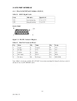
2.3.2 INTERFACE PORT
The T-96SR signals are defined as DCE. Connection to user DTE is made via a DE-15 female connector.
This connection meets the Dataradio Interoperability Standard (DI-OS).
Users can build a suitable cable by referring to the connector and cable pinout (see Figure 2-3 and
Table 2-4). For user data, pin 15 (DTR/PGM) should not be connected. A data cable for connection to a PC
type DE-9 connector is available from DRL (Part No. 697-0000-001).
Important Note:
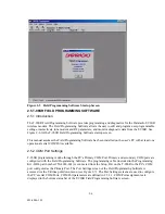
The T-96SR Field Programming Software, used to configure the T-96SR, includes a
special setup cable.
Do not use this cable to connect a user application.
Using this cable for user
application will result in the T-96SR switching to setup mode in which case the T-96SR will not transmit or
receive user data. The green LED flashes to indicate the unit is in setup mode.
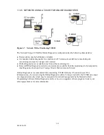
1
6
5
11
15
10
9 DCD (ORN)
8 RTS (WHT/BLK)
7 CTS (BLU)
4 TEST AUDIO (ORN/BLK)
3 TXD(RED)
2 RXD (WHT)
11 CS0 (GRN/BLK)
12 CS1 (BLU/WHT)
13 CS2 (RED/WHT)
14 RSSI (BLK/WHT)
15 DTR/PGM (BLK)
B+ (RED) (PINS 5-10)
B- (BLK) (PINS 1-6)
DE-15 TO
PIGTAIL FOR POWER
PN 023-3276-007
SHIELD