


SECTION 2
OPERATION AND CONNECTION
2-1
001-4006-101
2.1 INTRODUCTION
2.1.1 GENERAL
This section outlines the operation and connections of the T-96SR.
2.2 FRONT PANEL
2.2.1 INTRODUCTION
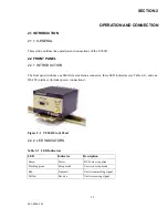
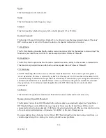
The front panel includes one SMA female antenna connector, three LED indicators (see Table 2-1), and one
DE-15F interface (includes power connections).
Figure 2-1 T-96SR Front Panel
2.2.2 LED INDICATORS
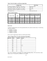
Table 2-1 LED Indicators
LED
Indicates
Description
Green
Power
DC Power is applied
Flashing green
Setup mode
Unit is in setup mode
Red
Transmit
Unit is transmitting signal
Yellow
Receive
Unit is receiving signal