Dataradio T-96SR Installation Manual Download Page 13

1-6

001-4006-101

1.8 REPLACEMENT PARTS

This product is not field serviceable, except by the replacement of complete units. Specialized equipment 
and training is required to repair logic boards and radio modules. 

1.9 IF A PROBLEM ARISES...

Component level repair is not recommended on the T-96SR. DRL’s factory is best equipped to diagnose 
problems and make component level repairs. Contact Technical Service before returning equipment. A 
service technician may suggest a solution eliminating the need to return equipment.

1.9.1  FACTORY REPAIR

Dataradio products are designed for long life and failure-free operation. If a problem arises, factory service 
is available. Contact the Technical Service Department before returning equipment. 

A Return Material Authorization (RMA) is required when returning equipment to Dataradio for repair. 
Contact the Technical Service Department at 1-800-992-7774 or 1-507-833-8819 (extension 6707) to 
request an RMA number. RMA’s are available through our website at www.dataradio.com/
products_tech_adv.html. Be prepared to give the equipment model and serial number, your account number 
(if known), and billing and shipping addresses.

Include the RMA number, a complete description of the problem, and the name and phone number of a 
contact person with the returned units. This information is important. The technician may have questions 
that need to be answered to identify the problem and repair the equipment. The RMA number helps locate 
your equipment in the repair lab if there is a need to contact Dataradio concerning the equipment. 

Units sent in for repair will be returned to the customer re-tuned to the current Dataradio Test and Tune 
Procedure and will conform to all specifications noted in this section 

Customers are responsible for shipping charges (to Dataradio) for returned units in warranty. Units in 
warranty are repaired free of charge unless there is evidence of abuse or damage beyond the terms of the 
warranty. Dataradio covers return shipping costs for equipment repaired while under warranty. 

Units out of warranty are subject to repair service charges. Customers are responsible for shipping charges 
(to and from Dataradio) on units out of warranty. Return shipping instructions are the responsibility of the 
customer.

1.10 EQUIPMENT DESCRIPTION 

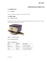
1.10.1  PHYSICAL DESCRIPTION

The T-96SR consists of a logic printed circuit board (PCB) (which includes the modem circuitry) and a 
separate radio module. The two boards plug directly together and slide into the rails of an extruded 
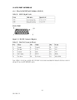
aluminum case. The front panel includes the DE-15 data connector and an SMA antenna connector, as well 
as three LED indicators. Power connections are made through the DE-15 data connector. The unit is not 
hermetically sealed and should be mounted in a suitable enclosure where dust and/or a corrosive atmosphere 
are anticipated. There are no external switches or adjustments. Operating parameters are set using software.

Summary of Contents for T-96SR

Page 1: ...S e r v i c e M a n u a l Synthesized T 96SR Hi Spec Integrated Wireless Modem...

Page 2: ...Synthesized T 96SR Hi Spec Wireless Modem Installation Manual January 2004 001 4006 101 Revision 9 1999 by Dataradio COR Ltd...

Page 3: ...est and most trusted in the industry Product Warranty The manufacturer s warranty statement for this product is available in our manuals or by contacting COR Ltd 299 Johnson Avenue P O Box 1733 Waseca...

Page 4: ...NG 1 7 ONLINE DIAGNOSTICS 1 8 OFFLINE DIAGNOSTICS 1 8 REMOTE COMMANDS 1 8 1 12 NETWORK CONFIGURATION 1 9 GENERAL 1 9 BASIC NETWORK 1 9 NETWORK USING T BASE 1 10 NETWORK USING T BASE REPEATER 1 10 NETW...

Page 5: ...35 END TO END TEST 2 35 2 6 T 96SR HELP FILES 2 38 2 7 OPTIMIZING YOUR SYSTEM 2 38 3 GLOSSARY DEFINITIONS 3 1 APPENDIX T 96SR VHF CERTIFICATE OF CONFORMITY A 1 T 96SR UHF CERTIFICATE OF CONFORMITY A 2...

Page 6: ...RTUP SCREEN 2 6 2 6 PORT SETTINGS SCREEN 2 7 2 7 PORT STATISTICS SCREEN 2 9 2 8 SETUP MODEM RADIO SCREEN 2 10 2 9 NETWORK TYPE CONNECTED TO A T 96SR MODEM 2 14 2 10 NETWORK TYPE CONNECTED TO A T 96S D...

Page 7: ...board Added End to End Test information to Section 2 Revision 6 April 2002 Updates to manual to reflect RF board change corrected screen images Revision 5 October 2001 Updated Table 2 7 added Signal...

Page 8: ...5 W software controlled z Half duplex or simplex operation z Transmit control via RTS z Online diagnostics monitoring z Offline local and remote diagnostics z Compatible with Dataradio T Base for bas...

Page 9: ...ctions found in this manual and the National Electrical Code ANSI NFPA70 Division 2 Hazardous classified Location Incendive Wiring Techniques Mount the unit in an enclosure or assembly Route all inter...

Page 10: ...1 3 001 4006 101 Figure 1 2 Installation Mounting Dimensions...

Page 11: ...frequenza Il fornitore di questo dispositivo non e responsabile per l uso non autorizzato O aviso advertir importante no uso restritivo estados de todo o membro do EU e do EFTA Este dispositivo um tr...

Page 12: ...that number Figure 1 3 Transceiver Identification Nomenclature 1 6 PRODUCT WARRANTY Dataradio warranties are available in Appendix B and are included in pdf format on CD versions of Dataradio manuals...

Page 13: ...to be answered to identify the problem and repair the equipment The RMA number helps locate your equipment in the repair lab if there is a need to contact Dataradio concerning the equipment Units sent...

Page 14: ...3 Diagnostics and Commands Online Diagnostics Information is automatically sent by each unit at the beginning of every transmission May be disabled for back compatibility with Dataradio T Modem 96 or...

Page 15: ...or the last 15 stations heard The accumulated values can be displayed using the Offline Diagnostics utility or can be dynamically monitored using the Online Diagnostics utility 1 11 5 OFFLINE DIAGNOST...

Page 16: ...2 through 1 12 5 describe network configurations 1 12 2 BASIC NETWORK Figure 1 4 Basic Network The Basic Network configuration has the following characteristics z Master station may be half duplex or...

Page 17: ...of T Base z The T Base provides output of Online Diagnostic information which can be processed by the T 96SR Online Diagnostics utility or by a user supplied network management program Contact your s...

Page 18: ...onitoring site z Remote Offline Diagnostics statistics and control are available from the monitoring site by temporarily disabling network activity best if using a Master Station Antenna System Online...

Page 19: ...6 MHz except 20 MHz 450 470 32 MHz Nominal Dimensions 2 212 H x 3 25 W x 4 585 L Shipping Weight 1 20 lbs 0 55 Kg RF connector SMA F Interface connector DE 15F high density D subminiature RECEIVER VHF...

Page 20: ...l Protocol Transparent to the user DISPLAY and CONTROLS 3 status LEDs RX TX PWR DIAGNOSTICS Online Supply voltage internal temperature forward and reverse power RSSI Offline As for online plus analog...

Page 21: ...nel includes one SMA female antenna connector three LED indicators see Table 2 1 and one DE 15F interface includes power connections Figure 2 1 T 96SR Front Panel 2 2 2 LED INDICATORS Table 2 1 LED In...

Page 22: ...channel selection control is desired If not use 697 0000 001 cable Table 2 2 RS 232 Signal Levels Term Alternates Signal level ON asserted spacing 3 to 15 V OFF dropped marking 3 to 15 V Table 2 3 Da...

Page 23: ...available from DRL Part No 697 0000 001 Important Note The T 96SR Field Programming Software used to configure the T 96SR includes a special setup cable Do not use this cable to connect a user applic...

Page 24: ...TE Tx Data Transmit Data from DTE to T 96SR CTS Clear to Send Asserted when the T 96SR is ready to accept Tx data RTS Request to Send Causes the T 96SR to transmit when asserted by the DTE DCD Data Ca...

Page 25: ...By strapping connections on the Data Port Connector There is a 10k ohm pull up resistor on each line CS0 to CS2 refer to Table 2 5 or making changes with the T 96SR Field Programming Software 2 By sel...

Page 26: ...n the user s PC with at least one operational serial COM Port available 2 5 2 COM Port Settings T 96SR programming is done through the PC s Primary COM Port Primary and secondary COM ports are configu...

Page 27: ...ects the communication speed for Primary and Secondary COM Ports Data Bits Selects the number of data bits 4 8 transmitted or received for the Primary and Secondary COM Ports Parity Selects transmissi...

Page 28: ...tings Communications Modes The Mode drop down menu configures the communications mode for the Primary and Secondary PC Port See Table 2 6 for Communication Modes configurations Table 2 6 Communication...

Page 29: ...RTS shows the current state of the RTS request to send line RTS is an output from the PC DTR DTR shows the current state of the DTR data terminal ready line DTR is an output from the PC CTS CTS shows...

Page 30: ...ast opened or cleared 2 5 4 Setup Modem Radio Parameters Figure 2 8 Setup Modem Radio Screen The Setup Modem Radio Parameters screen is accessed from the Edit menu pull down or from the Parms icon whe...

Page 31: ...ort ID is derived from the longer ID Number It is used to identify units and minimizes the time required to transmit Online Diagnostics The Short ID of each unit in a network must be unique if Online...

Page 32: ...ta frame and is susceptible to extraneous bits dribble bits at the end of data transmission The default value is Disabled unchecked Values are 4800 b s 16 ms 9600 b s 8 ms 19200 b s 4 ms An end of tra...

Page 33: ...n Baud Rates Full Channel T 96SR in T 96SR Native network type 4800 9600 19200 Half Channel T 96SR in T 96SR Native network type 4800 9600 Full Channel T 96SR in T 96S DL3276 network type 4800 9600 Ha...

Page 34: ...6 crystal units with serial numbers below 103500 The buffer icon to the right of his option will turn to an inverting buffer when Compatible is selected Choose Enhanced for other applications to achie...

Page 35: ...00 for full channel units or 1200 2400 4800 for half channel units Data Types offer two options Enhanced and Compatible Com patible causes the buffer icon to change to an inverting buffer 2 Crystal av...

Page 36: ...stuck transmitter The time is selected by a slider bar The range is 0 to 120 seconds with a default of 30 seconds Warning Transmissions longer than 30 seconds may exceed the duty cycle rating of the...

Page 37: ...reshold indicates the RSSI level when a carrier is lost This level should be less than the Carrier Detect On 2 5 4 5 Setup Modem Radio Frequencies The Frequencies tab provides the interface to program...

Page 38: ...n into the PC s memory To load parameters into the T 96SR initiate a Write Programmable Settings from the Edit menu or select the Write icon from the Tool Bar After the programmable parameters are loa...

Page 39: ...e Data File dat into multiple modems Note The Clone Programmable Parameters feature should be used instead of the Write Programmable Parameters whenever multiple radios are being programmed with ident...

Page 40: ...than the low Alarm and a character will designate a value greater than the High Alarm When Online Diagnostics are received and a diagnostic field falls outside the Filter Limits the diagnostic informa...

Page 41: ...t Local ID The Local ID is the Long ID of the unit connected to the computer The Short ID is displayed Remote ID The Remote ID combo box allows selection of the unit by choosing it s Remote ID from wh...

Page 42: ...used to begin the test Pause Pause is used to pause the test and allows the user to resume the test at a later time 2 5 10 OFFLINE DIAGNOSTICS Offline Diagnostics are returned from a local or remote u...

Page 43: ...with Preamble Good this serves as an indication of how well the unit is receiving data z Preamble DCD this number shows a count of all received Carrier Detects Figure 2 17 Offline Diagnostics Screen...

Page 44: ...ward power in Watts Reverse Power Reverse Power shows reverse power in Watts RSSI Panel The RSSI panel shows the current RSSI level in dBm while the local unit is receiving Modem Select Local ID The L...

Page 45: ...nostics The command is sent to the unit connected to the computer if the Local ID button is selected The command is sent to the selected Remote ID if the Remote ID and Selected Remote ID buttons are s...

Page 46: ...ostics does not require suspension of network operation Online Diagnostics are subject to alarm and filter conditions defined in the Diagnostic IDs Alarms and Filters screen see Figure 2 15 When Onlin...

Page 47: ...nostics were received Filter Filter allows the user to filter Short IDs The following options are available z Off All IDs no IDs are filtered out z ID List only the IDs in the Filter ID List are shown...

Page 48: ...r to save the current Online Diagnostics to a file A maximum of 4096 lines of data can be saved 2 5 12 USER TEST Figure 2 19 User Test Screen The User Test utility is an Offline function and requires...

Page 49: ...15 Used with Preamble Good this serves as an indication of how well the unit is receiving data RSSI This panel shows the current RSSI level in dBm while the local unit is receiving Rx Tx Frequency Rx...

Page 50: ...t Packets Rx ed Host Packets received shows the number of data packets the Host device has received from the Remote Remote to Host Remote to Host percentage shows the number of packets the Remote devi...

Page 51: ...ce This option requires a computer with 2 COM ports z Host Remote 1 Port using a Y cable Configures the primary COM port as the Host and Remote device A Y cable is required for this option with transm...

Page 52: ...rstuvwxyz 998 ABCDEFGHIJKLMNOPQRSTUVWXYZabcdefghijklmnopqrstuvwxyz 999 ABCDEFGHIJKLMNOPQRSTUVWXYZabcdefghijklmnopqrstuvwxyz 000 ABCDEFGHIJKLMNOPQRSTUVWXYZabcdefghijklmnopqrstuvwxyz 001 ABCDEFGHIJKLMNO...

Page 53: ...FF 02 11 22 33 44 55 66 77 88 99 AA BB CC DD EE FF 11 22 33 44 55 66 77 88 99 AA BB CC DD EE FF z Random Binary Pattern The packets will be 16 characters in length and contain random binary data of P...

Page 54: ...tion set up in the Port Settings screen Figure 2 22 ASCII Terminal Screen 2 5 15 1 ASCII Terminal ASCII Terminal configurations include Primary The Primary ASCII Terminal screen sends and receives ASC...

Page 55: ...dems The testing setup requires a computer running the Field Programming Software attached to each user COM port on the T 96SR wireless modems The Utilities will allow the user to send ASCII text or H...

Page 56: ...6SR through the computer s primary port once the Send button is clicked The sent ASCII message is then displayed in the Tx Data area of the ASCII Terminal window as shown in Figure 2 24 Figure 2 24 En...

Page 57: ...utility can be used to verify a communication path The previous procedure can also be used with the Hex Terminal utility When the Hex Terminal is used the information is entered as hex code Figure 2 2...

Page 58: ...e for a response T 96SR adds a short amount of delay to each poll and response typically in the order of 60 to 70 ms Timer settings that are too short may cause erroneous indication of missed polls in...

Page 59: ...100 dBm Approximately 50 reliability Fading may cause frequent data loss 90 dBm Approximately 90 reliability Fading will cause occasional data loss 80 dBm Approximately 99 reliability Reasonable tole...

Page 60: ...based on a forward power of 5 watts it may be scaled for lower power settings and gives guidelines to interpreting these figures Should values returned by the built in diagnostics seem to indicate a p...

Page 61: ...ive frequencies but which may not transmit and receive simultaneously PLC Programmable Logic Controller An intelligent device that can make decisions gather and report information and control other de...

Page 62: ...HE CONFORMITY ASSESSMENT PROCEDURE REFERRED TO IN ARTICLE 10 5 AND ANNEX IV DESCRIPTION OF THE PRODUCT Manufacturer Dataradio COR Ltd Address 299 Johnson Avenue Waseca Minnesota United States of Ameri...

Page 63: ...ASSESSMENT PROCEDURE REFERRED TO IN ARTICLE 10 5 AND ANNEX IV DESCRIPTION OF THE PRODUCT Manufacturer Dataradio COR Ltd Address 299 Johnson Avenue Waseca Minnesota United States of America Product Bra...

Page 64: ...v1 2 1 EN 60950 February 2000 February 1999 1992 incl A1 1993 A2 1993 A3 1995 A4 1997 and therefore complies with the essential requirements and provisions of the Directive 1999 5 EC of the European P...

Page 65: ...v1 2 1 EN 60950 February 2000 February 1999 1992 incl A1 1993 A2 1993 A3 1995 A4 1997 and therefore complies with the essential requirements and provisions of the Directive 1999 5 EC of the European P...

Page 66: ...declare under our sole responsibility that for the following equipment Description High Speed Transparent Radiomodem Transceiver Series Brand Trademark DATARADIO Model numbers 242 4016 xxx T 96SR VHF...

Page 67: ...Appendix A 6 001 4006 101 CSA Certificate...

Page 68: ...ed to replace or repair any Products if i the Product has been used in other than its normal and customary manner ii the Product has been subject to misuse accident neglect or damage or has been used...

Page 69: ...or damage or has been used other than with DRL approved accessories and equipment iii unauthorized alterations or repairs have been made or unapproved parts have been used in the Product or iv Buyer...

Reviews: