Electrical Installation
30
DX8210 Barcode Scanner
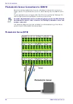
Photoelectric Sensor Connections to CBX510
Barcode scanning applications may use a Datalogic photoelectric sensor as a
trigger device. The photoelectric sensor is wired directly into the CBX510 termi-
nal.
If your application uses a trigger other than the one specified by Datalogic, fol-
low the appropriate wiring diagram to assure proper wiring.
The following diagrams illustrate standard recommended wiring of the Photo-
electric Sensor to the CBX510 terminal block.
Photoelectric Sensor (NPN)
To confirm the photoelectric sensor is functioning properly, watch the TRIG LED while
the photoelectric sensor’s beam is blocked. The Datalogic photoelectric sensor also
includes a status LED.
Summary of Contents for DX8210
Page 1: ...DX8210 Reference Manual Omnidirectional Barcode Scanner ...
Page 31: ...Installation Reference Manual 19 Small Side Mounted L Bracket Options ...
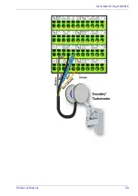
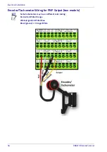
Page 45: ...Tachometer Wiring to CBX510 Reference Manual 33 ...
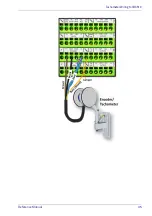
Page 47: ...Tachometer Wiring to CBX510 Reference Manual 35 ...
Page 49: ...Digital Output Configuration to CBX510 Reference Manual 37 Unpowered Outputs Powered Outputs ...
Page 268: ...Barcode Scanning Features 256 DX8210 Barcode Scanner DX8210 2100 0 25 mm 10mil ...
Page 269: ...Reading Diagrams Reference Manual 257 DX8210 2100 0 30 mm 12mil ...
Page 270: ...Barcode Scanning Features 258 DX8210 Barcode Scanner DX8210 2100 0 38 mm 15mil ...
Page 271: ...Reading Diagrams Reference Manual 259 DX8210 2100 0 50 mm 20 mil ...
Page 272: ...Barcode Scanning Features 260 DX8210 Barcode Scanner DX8210 4100 0 38 mm 15 mil ...
Page 273: ...Reading Diagrams Reference Manual 261 DX8210 4100 0 50 mm 20 mil ...
Page 274: ...Barcode Scanning Features 262 DX8210 Barcode Scanner DX8210 4200 0 25 mm 10 mil ...
Page 275: ...Reading Diagrams Reference Manual 263 DX8210 4200 0 30 mm 12 mil ...
Page 297: ...Reference Manual 285 ...
Page 298: ......
Page 299: ......


