


SOFTWARE
55
4
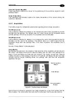
AUTO
: illuminators are normally off and turn on only during the passage of packs in the
reading field. This mode is only available for LED illuminators.
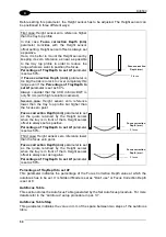
Tunnel Length
This parameter indicates the reading station tunnel length. Generally it corresponds to the
distance from the Trigger Sensor to the more distant view line.
When the trigger is ON, the illuminators are switched on and will be switched off only after
the package has passed the reading line.
Usually a value longer than the real tunnel length is set to have the illuminators switched off
with a short delay.
Switch Off timeout
This parameter allows setting a delay after which the illuminators will be switched off even if
the package has not yet passed under the reading line, for example when the conveyor is
stopped and the package is still inside the tunnel.
It is recommended to set a delay value higher than the time a package needs to go from the
trigger sensor to the reading line, so that the illuminators will not switch off too early.
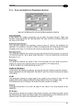
Illuminator 1-2…6
These sections contain parameters relative to each specific illuminator.
Power
This parameter indicates the illuminating power. It is possible to regulate the power between
50% and 100%.
Description
This string appears as a description of the specific illuminator in all setup and supervision
tools. It usually describes the position of the illuminator on the multi-sided reading station.
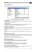
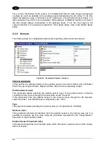
4.2.8 Decoder
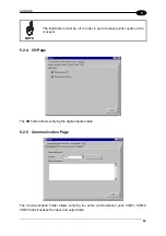
Communication
This folder groups the configuration parameters regarding the communication protocol with
the PC (DD9500) Decoder.
Protocol
This parameter indicates the type of protocol used. The default setting is “DL Standard” but it
can be modified for a custom configuration.
Camera Link Serial Port
By enabling this parameter the RS232 serial port of the Camera Link connector is enabled. In
this way, the serial communication with the PC Decoder (DD9500) is made through the
Camera Link cable.
CAUTION
When this parameter is enabled the camera COM1 connector will
automatically be isolated.
Setting this parameter using a connection on this port will produce an
error during the check phase of the save procedure.
The yellow LED "USER DEF" on the camera back panel switches on when this parameter is
enabled.
Summary of Contents for DV9500 Series
Page 1: ...DV9500 Installation Manual ...
Page 2: ......


