FOCUSING SETUP AND CALIBRATION
248
AV7000 LINEAR CAMERA
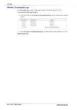
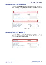
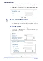
3. Under
Message Format
, select
Camera Focus
from the
Focus messages for Data-
logic cameras
drop-down list.
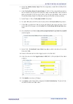
4. Select the
Model
of camera for which you are focusing.
5. Enter the
Focus Transmit Point
. This is the distance the DM3610 waits until after
the AV7000 scan line has read, to transmit the message. This value correlates to a
value in the AV7000 settings. Default is 8 inches.
6. Enter the
Focus Transmit Interval
. This is the amount of milliseconds between
data transmissions. It defines the frequency of the data transmissions from the
DM3610(s).
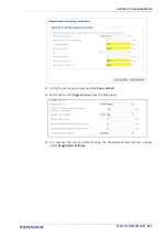
7. Click
Update
to save the changes.
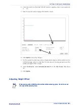
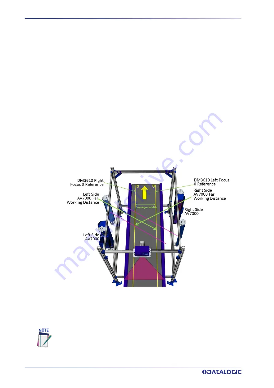
8. The distance between the far working distances of the cameras is considered the
“Conveyor Width” and must also be entered in the
Conveyor Width
field in
AV7000
Global Settings | Operating Mode.
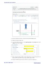
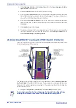
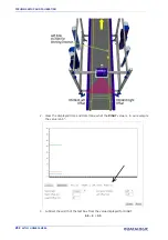
Understanding DM3610 Focusing and AV7000 System Orientation
The goal of this focusing process is to correlate the DM3610 zero reference points to the
far working distances of the cameras.
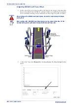
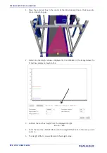
The DM3610 Left and Right Offsets focus the DM3610 at the
Far Working Distances
(Left and Right)
of the side AV7000 cameras. These values are not necessarily the same.
Reference the system application drawings for the exact prescribed Far Working Dis-
tances of each camera.
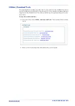
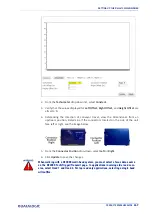
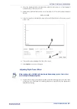
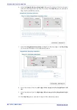
1. Navigate to
Diagnostics | Focus Setup
. The
Focus Setup
window opens.
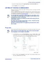
If you navigate away from the Focus Setup page, the Constant Tach setting will auto-
matically reset to Hardware Tach. Reset it, to continue the focus setup process.
Summary of Contents for AV7000
Page 1: ...AV7000 PRODUCT REFERENCE GUIDE Linear CAMERA...
Page 48: ...MECHANICAL INSTALLATION 34 AV7000 LINEAR CAMERA...
Page 49: ...INSTALLATION SEQUENCE PRODUCT REFERENCE GUIDE 35...
Page 55: ...INSTALLING THE DEFLECTION MIRROR PRODUCT REFERENCE GUIDE 41...
Page 57: ...INSTALLING THE DEFLECTION MIRROR PRODUCT REFERENCE GUIDE 43...
Page 60: ...MECHANICAL INSTALLATION 46 AV7000 LINEAR CAMERA...
Page 66: ...ELECTRICAL INSTALLATION 52 AV7000 LINEAR CAMERA Controller Client Array with DM3610...
Page 69: ...TYPICAL CONNECTION BLOCK DIAGRAMS PRODUCT REFERENCE GUIDE 55 AV7000 in Hybrid Configuration...
Page 80: ...ELECTRICAL INSTALLATION 66 AV7000 LINEAR CAMERA Photoelectric Sensor to CBX510 PNP...
Page 96: ...ELECTRICAL INSTALLATION 82 AV7000 LINEAR CAMERA Unpowered Outputs...
Page 97: ...CBX100 CBX510 CBX800 INITIAL CONFIGURATION PRODUCT REFERENCE GUIDE 83 Powered Outputs...
Page 116: ...E GENIUS 102 AV7000 LINEAR CAMERA...
Page 134: ...E GENIUS 120 AV7000 LINEAR CAMERA...
Page 175: ...PRODUCT REFERENCE GUIDE 161 4 Again run the small package through the system...
Page 239: ...PRODUCT REFERENCE GUIDE 225 12 Click Update to save your changes...
Page 278: ...FOCUSING SETUP AND CALIBRATION 264 AV7000 LINEAR CAMERA...
Page 309: ...READING LINEAR BARCODES PRODUCT REFERENCE GUIDE 295 READING LINEAR BARCODES...
Page 310: ...AV7000 FEATURES 296 AV7000 LINEAR CAMERA...
Page 311: ...PRODUCT REFERENCE GUIDE 297...
Page 312: ...AV7000 FEATURES 298 AV7000 LINEAR CAMERA...
Page 313: ...PRODUCT REFERENCE GUIDE 299 READING 2D BARCODES...
Page 314: ...AV7000 FEATURES 300 AV7000 LINEAR CAMERA...
Page 315: ...PRODUCT REFERENCE GUIDE 301...
Page 316: ...AV7000 FEATURES 302 AV7000 LINEAR CAMERA...
Page 336: ...TROUBLESHOOTING 322 AV7000 LINEAR CAMERA 4 Click Stop Acquiring to freeze the scope...
Page 350: ...TECHNICAL FEATURES 336 AV7000 LINEAR CAMERA...
Page 351: ......

