SETTING UP THE DM3610 DIMENSIONER
PRODUCT REFERENCE GUIDE
247
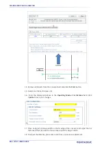
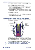
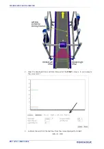
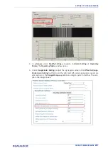
19. Enter this displayed value in the
Operating Mode > Far Distance Offset
field.
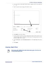
20. Click
Update
to save your changes.
SETTING UP THE DM3610 DIMENSIONER
DM3610 Dimensioners provide focus data for Datalogic cameras, including the AV7000,
NVS9000, and AV6010.
Refer to the
DM3610 Dimensioner Reference Manual
(or Two-Head Dimensioner Refer-
ence Manual) for complete information on installation and calibration of the DM3610. It
is available for download from
Preparation
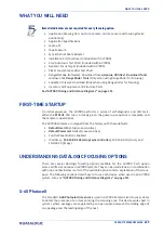
Before beginning the DM3610 focusing process, a few preliminary settings are required.
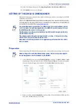
1. In the DM3610 e-Genius under
Modify Settings
, navigate to
Serial | Main
or
Aux
depending on the port wired to the AV7000 (typically
Main,
consult your applica-
tion interconnect diagrams for details). The
Serial | Main
window opens.
2. Make sure the selected
Baud Rate
matches that of the AV7000 (AV7000 uses the
main port, RS485 (RS422), at 115200).
For single Dimensioner applications, the DM3610 must be running software version
1.8.11 or greater. For multi-head applications, the DM3610’s must be running 1.8.1 and
the DC3000 must be version 1.3.60 or greater.
The Dimensioner scan line must be installed at least 500 mm [20 in] upstream from the
nearest camera scan line.
The examples used in this guide use Imperial units i.e. inches. If the system is config-
ured for metric, the unit of measure will be in mm.
Remember to reset these parameters to the application specifications after the calibra-
tion is complete.
When working with a multi-head Dimensioning system, the focus setup steps apply to
the unit designated as the “Tach Master” by the DC3000.
Summary of Contents for AV7000
Page 1: ...AV7000 PRODUCT REFERENCE GUIDE Linear CAMERA...
Page 48: ...MECHANICAL INSTALLATION 34 AV7000 LINEAR CAMERA...
Page 49: ...INSTALLATION SEQUENCE PRODUCT REFERENCE GUIDE 35...
Page 55: ...INSTALLING THE DEFLECTION MIRROR PRODUCT REFERENCE GUIDE 41...
Page 57: ...INSTALLING THE DEFLECTION MIRROR PRODUCT REFERENCE GUIDE 43...
Page 60: ...MECHANICAL INSTALLATION 46 AV7000 LINEAR CAMERA...
Page 66: ...ELECTRICAL INSTALLATION 52 AV7000 LINEAR CAMERA Controller Client Array with DM3610...
Page 69: ...TYPICAL CONNECTION BLOCK DIAGRAMS PRODUCT REFERENCE GUIDE 55 AV7000 in Hybrid Configuration...
Page 80: ...ELECTRICAL INSTALLATION 66 AV7000 LINEAR CAMERA Photoelectric Sensor to CBX510 PNP...
Page 96: ...ELECTRICAL INSTALLATION 82 AV7000 LINEAR CAMERA Unpowered Outputs...
Page 97: ...CBX100 CBX510 CBX800 INITIAL CONFIGURATION PRODUCT REFERENCE GUIDE 83 Powered Outputs...
Page 116: ...E GENIUS 102 AV7000 LINEAR CAMERA...
Page 134: ...E GENIUS 120 AV7000 LINEAR CAMERA...
Page 175: ...PRODUCT REFERENCE GUIDE 161 4 Again run the small package through the system...
Page 239: ...PRODUCT REFERENCE GUIDE 225 12 Click Update to save your changes...
Page 278: ...FOCUSING SETUP AND CALIBRATION 264 AV7000 LINEAR CAMERA...
Page 309: ...READING LINEAR BARCODES PRODUCT REFERENCE GUIDE 295 READING LINEAR BARCODES...
Page 310: ...AV7000 FEATURES 296 AV7000 LINEAR CAMERA...
Page 311: ...PRODUCT REFERENCE GUIDE 297...
Page 312: ...AV7000 FEATURES 298 AV7000 LINEAR CAMERA...
Page 313: ...PRODUCT REFERENCE GUIDE 299 READING 2D BARCODES...
Page 314: ...AV7000 FEATURES 300 AV7000 LINEAR CAMERA...
Page 315: ...PRODUCT REFERENCE GUIDE 301...
Page 316: ...AV7000 FEATURES 302 AV7000 LINEAR CAMERA...
Page 336: ...TROUBLESHOOTING 322 AV7000 LINEAR CAMERA 4 Click Stop Acquiring to freeze the scope...
Page 350: ...TECHNICAL FEATURES 336 AV7000 LINEAR CAMERA...
Page 351: ......


